CRC Control Registers
www.ti.com
656
SPNU563A–March 2018
Submit Documentation Feedback
Copyright © 2018, Texas Instruments Incorporated
Cyclic Redundancy Check (CRC) Controller Module
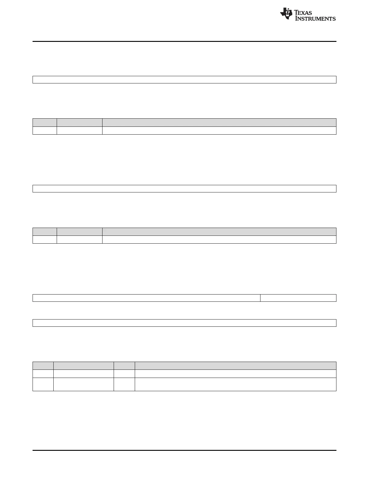
18.4.20 Channel 1 Raw Data Low Register (RAW_DATAREGL1)
Figure 18-28. Channel 1 Raw Data Low Register (RAW_DATAREGL1) [offset = 78h]
31 0
RAW_DATA1
R-0
LEGEND: R = Read only; -n = value after reset
Table 18-24. Channel 1 Raw Data Low Register (RAW_DATAREGL1) Field Descriptions
Bit Field Description
31-0 RAW_DATA1 Channel 1 Raw Data Low Register. This register contains bits 31:0 of the uncompressed raw data.
18.4.21 Channel 1 Raw Data High Register (RAW_DATAREGH1)
Figure 18-29. Channel 1 Raw Data High Register (RAW_DATAREGH1) [offset = 7Ch]
31 0
RAW_DATA1
R-0
LEGEND: R = Read only; -n = value after reset
Table 18-25. Channel 1 Raw Data High Register (RAW_DATAREGH1) Field Descriptions
Bit Field Description
31-0 RAW_DATA1 Channel 1 Raw Data High Register. This register contains bits 63:32 of the uncompressed raw data.
18.4.22 CRC Pattern Counter Preload Register 2 (CRC_PCOUNT_REG2)
Figure 18-30. CRC Pattern Counter Preload Register 2 (CRC_PCOUNT_REG2) [offset = 80h]
31 18 19 16
Reserved CRC_PAT_COUNT2
R-0 R/W-0
15 0
CRC_PAT_COUNT2
R/W-0
LEGEND: R/W = Read/Write; R = Read only; -n = value after reset
Table 18-26. CRC Pattern Counter Preload Register 2 (CRC_PCOUNT_REG2) Field Descriptions
Bit Field Value Description
31-20 Reserved 0 Reads return 0. Writes have no effect.
19-0 CRC_PAT_COUNT2 Channel 2 Pattern Counter Preload Register. This register contains the number of data
patterns in one sector to be compressed before a CRC is performed.