Address-Decoder
Transient Buffer Tx
Transient Buffer Rx
Shift Register
Control
Address
Data(31-0)
Data(31-0)
Txd1Rxd1
Control
Address
Data(31-0)
Data(31-0)
Txd2Rxd2
Shift Register
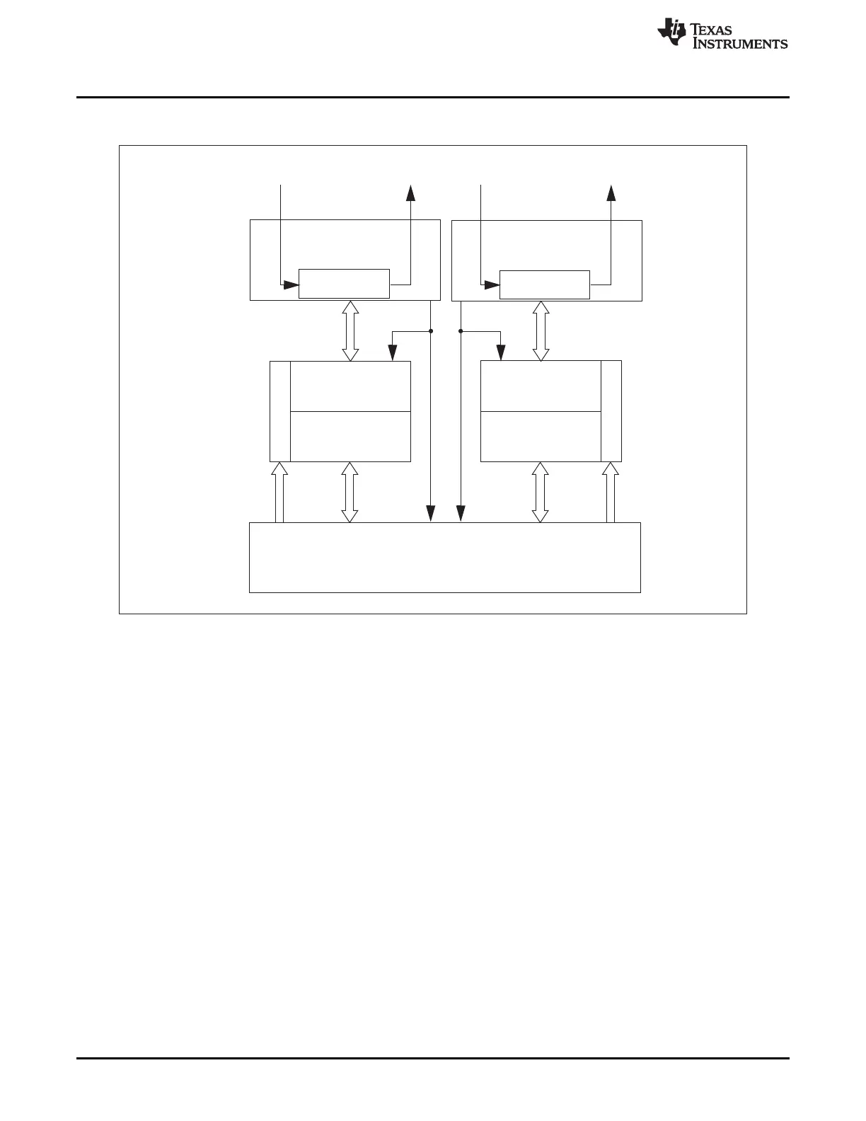
FlexRay PRT A FlexRay PRT B
Address-Decoder
Transient Buffer Tx
Transient Buffer Rx
Message Handler
TBF A TBF B
Module Operation
www.ti.com
1258
SPNU563A–March 2018
Submit Documentation Feedback
Copyright © 2018, Texas Instruments Incorporated
FlexRay Module
Figure 26-22. Access to Transient Buffer RAMs
26.2.13 Module RAMs
The FlexRay module contains the following RAM portions:
• Message RAM
• Transient Buffer RAM Channel A (TBF A)
• Transient Buffer RAM Channel B (TBF B)
• Input Buffer (IBF)
• Input Buffer Shadow (IBFS)
• Output Buffer (OBF)
• Output Buffer Shadow (OBFS)
• Transfer Configuration RAM (TCR)
All RAMs except the TCR are part of the Communication Controller core.
26.2.13.1 Message RAM
To avoid conflicts between host access to the message RAM and FlexRay message reception /
transmission, the host CPU cannot directly access the message buffers in the message RAM. These
accesses are handled through the input and output buffers. The message RAM is able to store up to 128
message buffers depending on the configured payload length.
The message RAM has a structure as shown in Figure 26-23.
The data partition is allowed to start at Message RAM word number: (MRC.LCB + 1) • 4

 Loading...


