www.ti.com
HWAG Registers
1051
SPNU563A–March 2018
Submit Documentation Feedback
Copyright © 2018, Texas Instruments Incorporated
High-End Timer (N2HET) Module
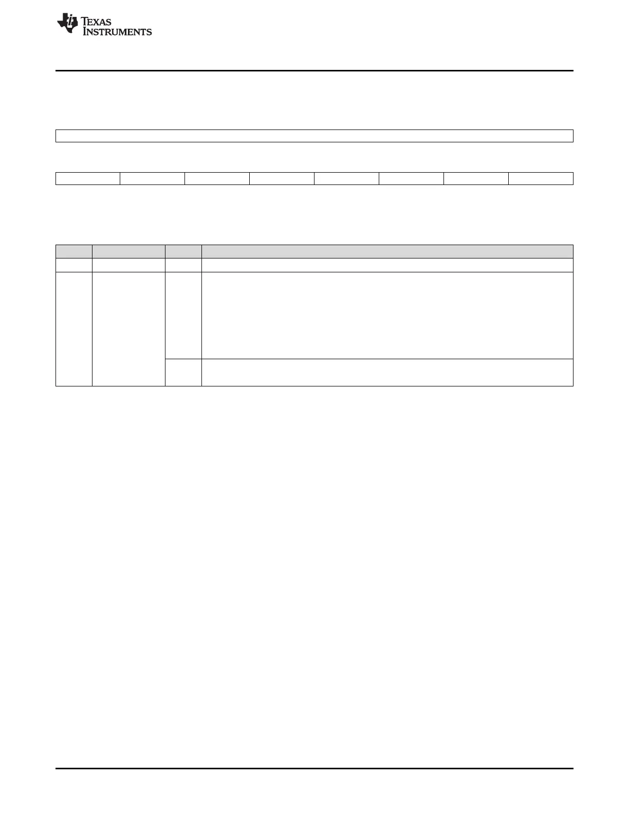
23.5.9 HWAG Interrupt Flag Register (HWAFLG)
Figure 23-97. HWAG Interrupt Flag Register (HWAFLG)
31 8
Reserved
R-0
7 6 5 4 3 2 1 0
INTFLG7 INTFLG6 INTFLG5 INTFLG4 INTFLG3 INTFLG2 INTFLG1 INTFLG0
R/W1C-0 R/W1C-0 R/W1C-0 R/W1C-0 R/W1C-0 R/W1C-0 R/W1C-0 R/W1C-0
LEGEND: R/W = Read/Write; R = Read only; W1C = Write 1 to clear; -n = value after reset
Table 23-61. HWAG Interrupt Flag Register (HWAFLG) Field Descriptions
Bit Field Value Description
31-8 Reserved 0 Reads return 0. Writes have no effect.
7-0 INTFLG[n] Interrupt Flag. These bit are set when an interrupt condition has occurred inside the HWAG. The
interrupt is sent to the CPU if, and only if, the corresponding enable bit is set. HWAFLG is cleared
by either reading the HWAOFF0 or HWAOFF1 register (if the corresponding bit is set) or by writing
1 to the bit. If HWAFLG is 1 but the corresponding interrupt is not enabled then it will not generate
an interrupt, also the OFFSET index will not be generated for that particular HWAFLG bit. So, a
read of HWAOFF registers will not clear a HWAFLG bit that is not enabled. See Table 23-57.
0 Read: No interrupt is pending.
Write: No effect.
1 Read: Interrupt is pending.
Write: Clear the corresponding interrupt flag.

 Loading...


