EMIF_CLK
Setup
Strobe pg_delay pg_delay pg_delay
Hold
EMIF_nCS[n]
EMIF_nDQM
EMIF_A/EMIF_BA A0 A1 A2 A3
D0 D1 D2 D3
EMIF_D
EMIF_nOE
EMIF_nWE
EMIF Module Architecture
www.ti.com
822
SPNU563A–March 2018
Submit Documentation Feedback
Copyright © 2018, Texas Instruments Incorporated
External Memory Interface (EMIF)
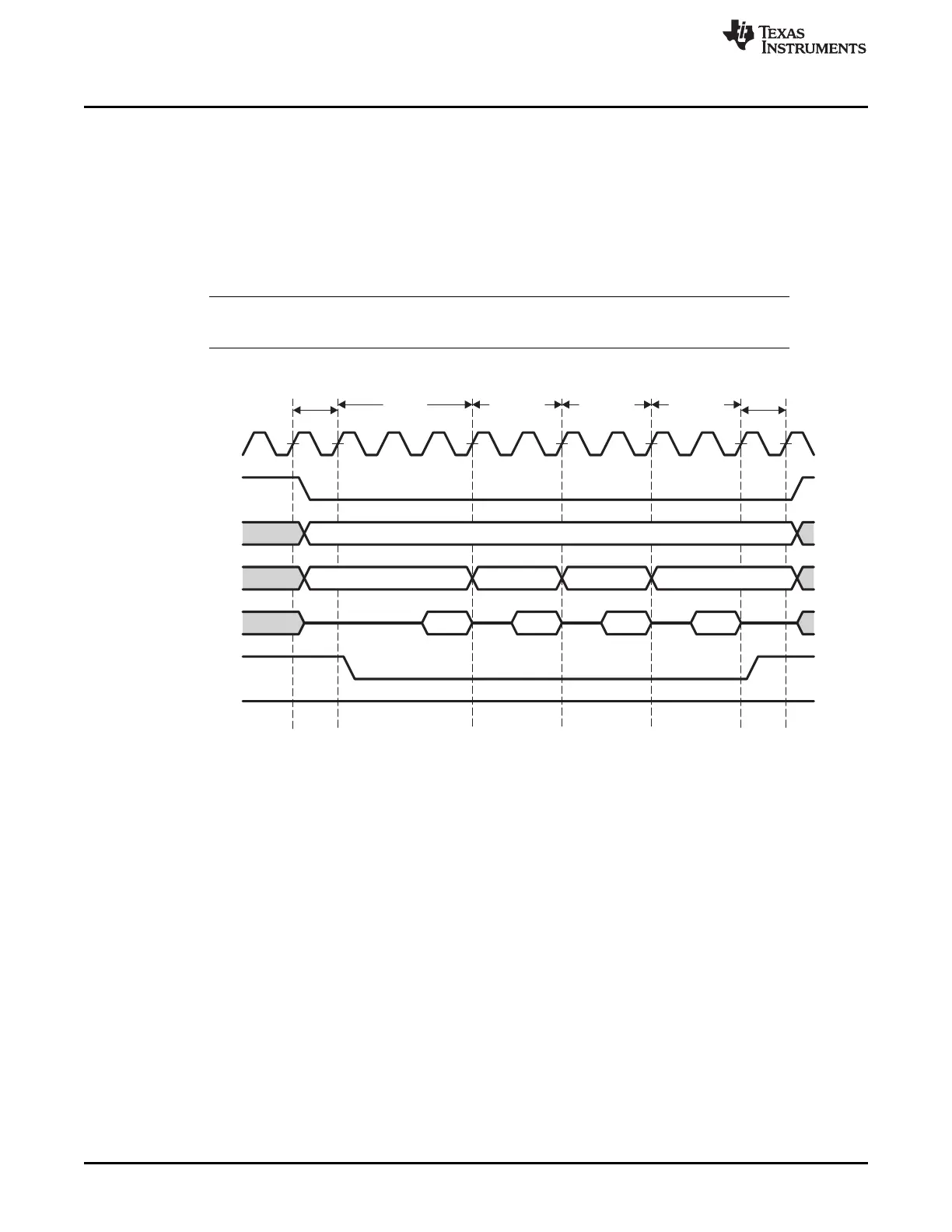
21.2.6.7 NOR Flash Page Mode
EMIF supports Page mode reads for NOR Flash on its asynchronous memory chip selects. This mode can
be enabled by writing a 1 to the CSn_PG_MD_EN (n = 2, 3, or 4) field in the Page Mode Control register
for the chip select in consideration. Whenever Page Mode for reads is enabled for a particular chip select,
the page size for the device connected must also be programmed in the CSn_PG_SIZE field of the Page
Mode Control register. The address change to valid read data available timing must be programmed in the
CSn_PG_DEL field of the Page Control register. All other asynchronous memory timings must be
programmed in the asynchronous configuration register (CEnCFG). See Figure 21-14 for read in
asynchronous page mode.
NOTE: The Extended Wait mode and the Select Strobe mode must be disabled when using the
asynchronous interface in Page mode.
Figure 21-14. Asynchronous Read in Page Mode
21.2.7 Data Bus Parking
The EMIF always drives the data bus to the previous write data value when it is idle. This feature is called
data bus parking. Only when the EMIF issues a read command to the external memory does it stop
driving the data bus. After the EMIF latches the last read data, it immediately parks the data bus again.
The one exception to this behavior occurs after performing an asynchronous read operation while the
EMIF is in the self-refresh state. In this situation, the read operation is not followed by the EMIF parking
the data bus. Instead, the EMIF tri-states the data bus. Therefore, it is not recommended to perform
asynchronous read operations while the EMIF is in the self-refresh state, in order to prevent floating inputs
on the data bus. External pull-ups, such as 10kΩ resistors, should be placed on the 16 EMIF data bus
pins (which do not have internal pull-ups) if it is required to perform reads in this situation. The precise
resistor value should be chosen so that the worst case combined off-state leakage currents do not cause
the voltage levels on the associated pins to drop below the high-level input voltage requirement.
For information about the self-refresh state, see Section 21.2.5.7.
 Loading...


