Static segment
Symbol
window
NIT
Communication cycle x
Communication
cycle x-1
Communication
cycle x+1
Time base
derived trigger
t
Time base
derived trigger
Dynamic
segment
Static segment
Dynamic segment
Module Operation
www.ti.com
1226
SPNU563A–March 2018
Submit Documentation Feedback
Copyright © 2018, Texas Instruments Incorporated
FlexRay Module
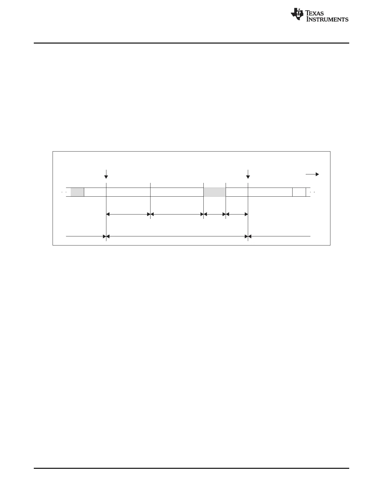
26.2.2 Communication Cycle
A communication cycle in FlexRay (Figure 26-10) consists of the following elements:
• Static segment
• Dynamic segment
• Symbol window
• Network idle time (NIT)
Static segment, dynamic segment, and symbol window form the network communication time (NCT). For
each communication channel the slot counter starts at 1 and counts up until the end of the dynamic
segment is reached. Both channels share the same arbitration grid which means that they use the same
synchronized macrotick.
Figure 26-10. Structure of Communication Cycle
26.2.2.1 Static Segment
The Static Segment is characterized by the following features:
• Time slots of fixed length (optionally protected by bus guardian)
• Start of frame transmission at action point of the corresponding static slot
• Payload length same for all frames on both channels
Parameters: number of static slots GTUC7.NSS(9-0), static slot length GTUC7.SSL(9-0), Payload Length
Static MHDC.SFDL(6-0), action point offset GTUC9.APO(5-0)
26.2.2.2 Dynamic Segment
The Dynamic Segment is characterized by the following features:
• All controllers have bus access (no bus guardian protection possible)
• Variable payload length and duration of slots, different for both channels
• Start of transmission at minislot action point
Parameters: number of minislots GTUC8.NMS(12-0), minislot length GTUC8.MSL(5-0), minislot action
point offset GTUC9.MAPO(4-0), start of latest transmit (last minislot) MHDC.SLT(12-0)
26.2.2.3 Symbol Window
During the symbol window only one media access test symbol (MTS) may be transmitted per channel.
MTS symbols are sent in NORMAL_ACTIVE state to test the bus guardian.
The symbol window is characterized by the following features:
• Send single symbol
• Transmission of the MTS symbol starts at the symbol windows action point

 Loading...


