STC Control Registers
www.ti.com
456
SPNU563A–March 2018
Submit Documentation Feedback
Copyright © 2018, Texas Instruments Incorporated
Self-Test Controller (STC) Module
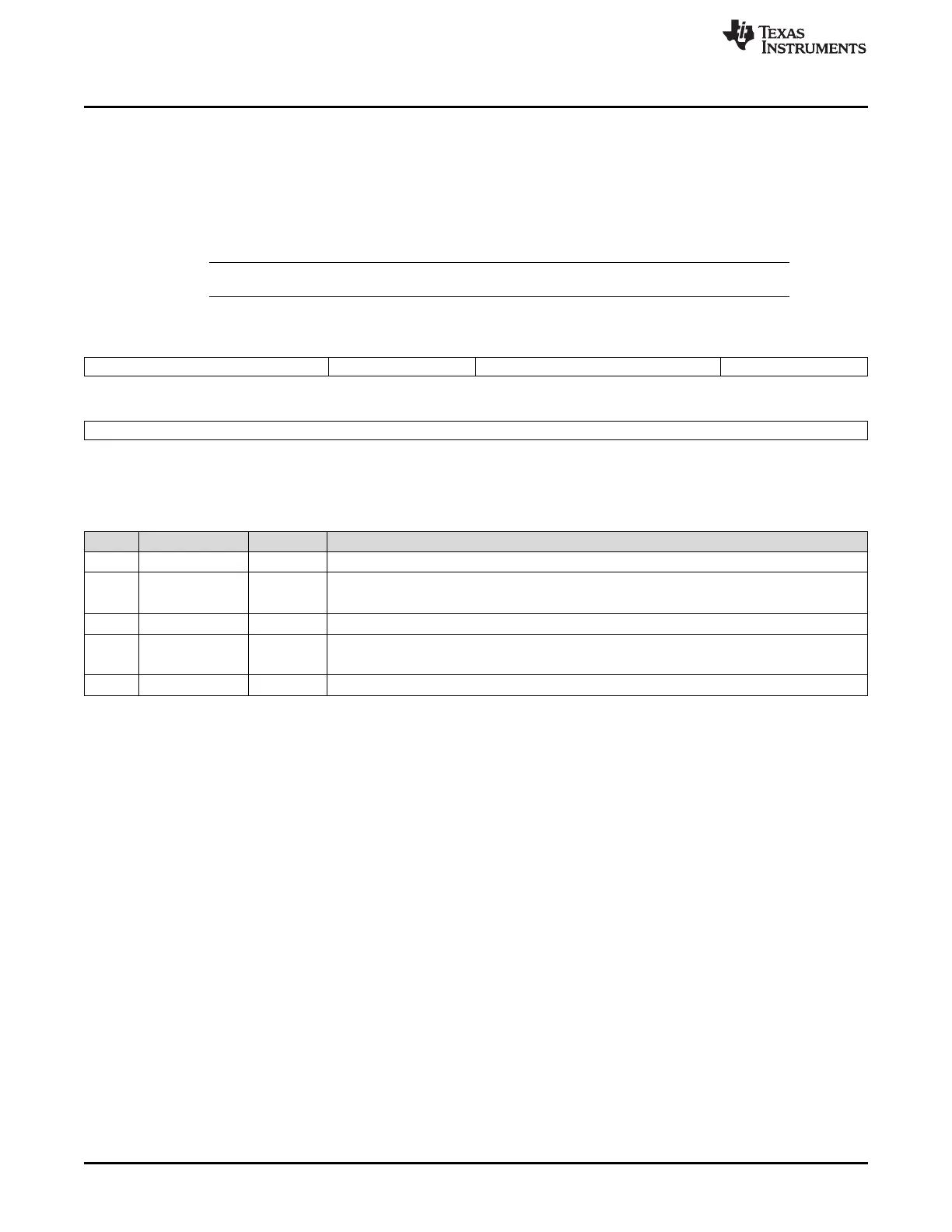
10.8.12 STC Clock Prescalar Register (STCCLKDIV)
This register is described in Figure 10-25. This register is used to configure STC clock divider ratio for
each segment. STCCLK is derived from the system clock (GCLK1 for STC1 and VCLK2 for STC2) and
the configured ratio is applied when the corresponding segment is under test. The division ratio
programmed in this register will have effect only when the value in the CLKDIV field of the STCLKDIV
register (FFFF E108h) from SYS2 module is zero. Else the division ratio will be taken from SYS2. This is
done for software compatibility.
NOTE: The clock divider ratio is applied when the corresponding segment is under test.
Figure 10-25. STC Clock Prescalar Register (STCCLKDIV) [offset = 44h]
31 27 26 24 23 19 18 16
Reserved CLKDIV0 Reserved CLKDIV1
R-0 R/WP-0 R-0 R/WP-0
15 0
Reserved
R-0
LEGEND: R/W = Read/Write; R = Read only; WP = Write in privilege mode only; -n = value after nPORST (power on reset) or System reset
Table 10-20. STC Clock Prescalar Register (STCCLKDIV) Field Descriptions
Bit Field Value Description
31-27 Reserved 0 Reads return 0. Writes have no effect.
26-24 CLKDIV0 STCCLK divider for segment 0.
0-7h Division ratio of segment 0 will be n+1. STCCLK clock will be divided by (n+1) for segment 0.
23-19 Reserved 0 Reads return 0. Writes have no effect.
18-16 CLKDIV1 STCCLK divider for segment 1.
0-7h Division ratio of segment 1 will be n+1. STCCLK clock will be divided by (n+1) for segment 1.
15-0 Reserved 0 Reads return 0. Writes have no effect.

 Loading...


