www.ti.com
PBIST Control Registers
415
SPNU563A–March 2018
Submit Documentation Feedback
Copyright © 2018, Texas Instruments Incorporated
Programmable Built-In Self-Test (PBIST) Module
9.5.3 PBIST Activate/Clock Enable Register (PACT)
This is the first register that needs to be programmed to activate the PBIST controller. Bit [0] is used for
static clock gating, and unless a 1 is written to this bit, all the internal PBIST clocks are shut off. Figure 9-5
and Table 9-4 illustrate this register.
NOTE: This register must be programmed to 1h during application self-test.
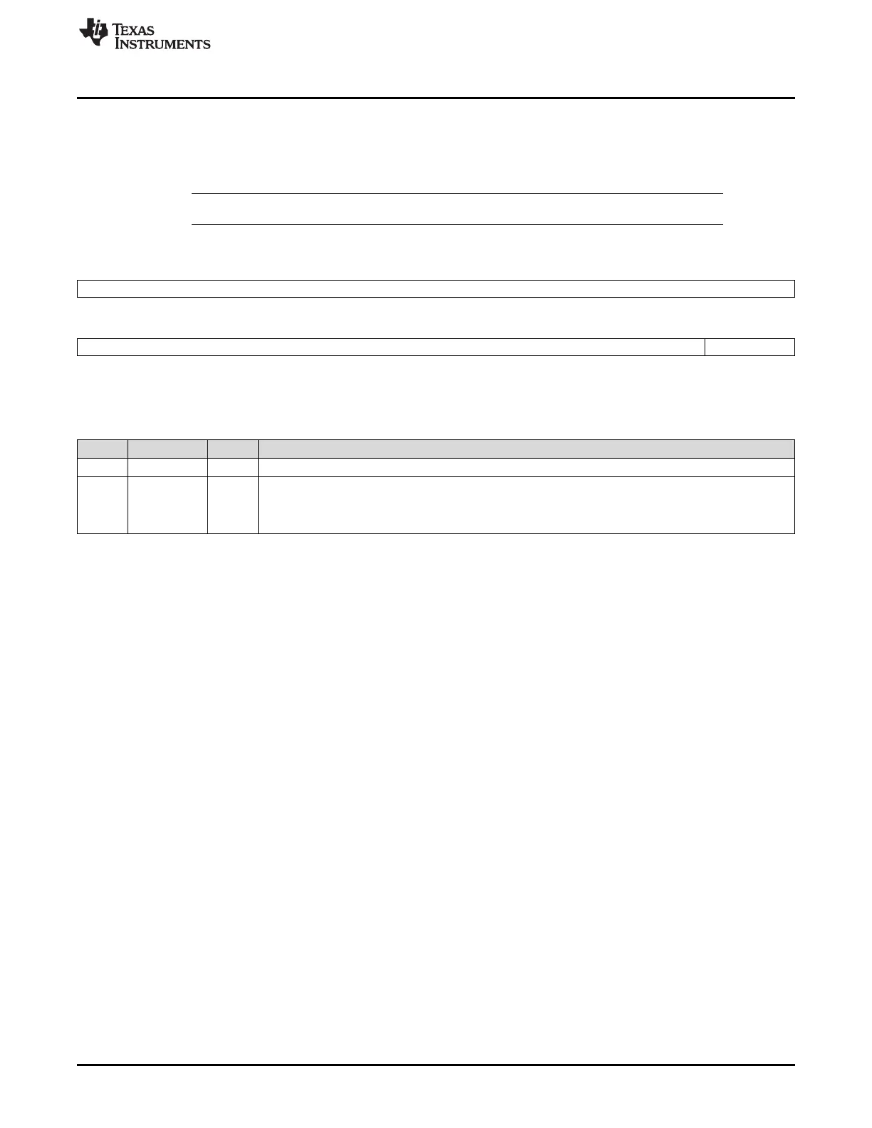
Figure 9-5. PBIST Activate/ROM Clock Enable Register (PACT) [offset = 0180h]
31 16
Reserved
R-0
15 1 0
Reserved PACT0
R-0 R/W-0
LEGEND: R/W = Read/Write; R = Read only; -n = value after reset
Table 9-4. PBIST Activate/ROM Clock Enable Register (PACT) Field Descriptions
Bit Field Value Description
31-1 Reserved 0 Reads return 0. Writes have no effect.
0 PACT0 PBIST internal clocks enable.
0 Disable PBIST internal clocks.
1 Enable PBIST internal clocks.
• PACT0
This bit must be set to 1 to turn on the PBIST internal clocks. Setting this bit asserts an internal signal that
is used as the clock gate enable. As long as this bit is 0, any access to the PBIST will not go through and
the PBIST will remain in an almost zero-power mode.

 Loading...


