ADC Registers
www.ti.com
940
SPNU563A–March 2018
Submit Documentation Feedback
Copyright © 2018, Texas Instruments Incorporated
Analog To Digital Converter (ADC) Module
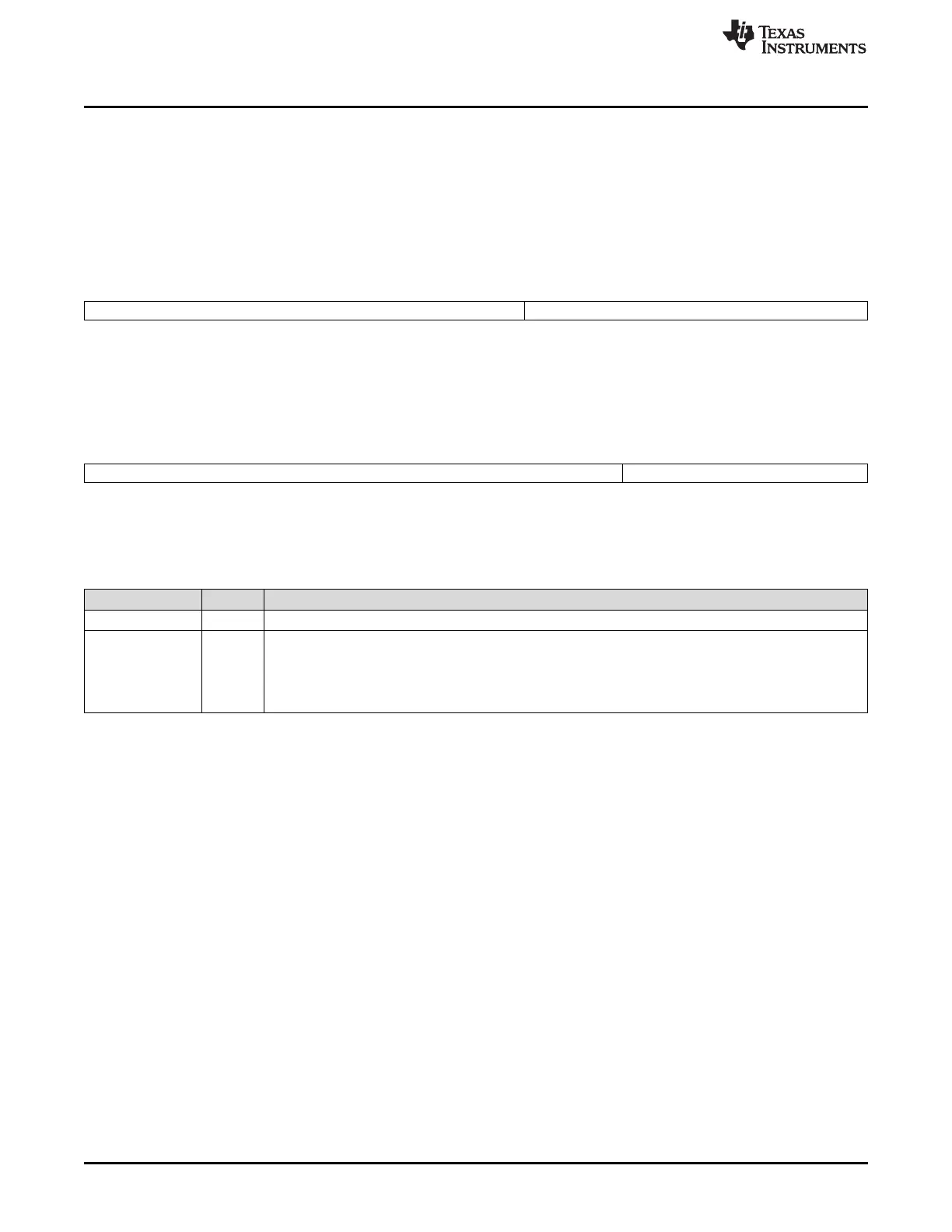
22.3.55 ADC Magnitude Compare Interruptx Mask Register (ADMAGINTxMASK)
ADC Magnitude Compare Interruptx Mask Register (ADMAGINTxMASK) is shown in Figure 22-85and
Figure 22-86, and described in Table 22-61. As shown, the format of the ADMAGINTxMASK is different
based on whether the ADC module is configured to be a 12-bit or a 10-bit ADC module. There are three
mask registers for the three magnitude compare interrupts. These registers are at offset addresses 12Ch,
134h, and 13Ch.
Figure 22-85. 12-bit ADC Magnitude Compare Mask Register (ADMAGINTxMASK)
[offset = 12Ch-13Ch]
31 12 11 0
Reserved MAG_INTx_MASK
R-0 R/W-0
LEGEND: R/W = Read/Write; R = Read only; -n = value after reset
Figure 22-86. 10-bit ADC Magnitude Compare Mask Register (ADMAGINTxMASK)
[offset = 12Ch-13Ch]
31 10 9 0
Reserved MAG_INTx_MASK
R-0 R/W-0
LEGEND: R/W = Read/Write; R = Read only; -n = value after reset
Table 22-61. ADC Magnitude Compare Interruptx Mask Register (ADMAGINTxMASK)
Field Descriptions
Field Value Description
Reserved 0 Reads return 0. Writes have no effect.
MAG_INTx_MASK These bits specify the mask for the comparison in order to generate the magnitude compare interrupt # x.
Any operation mode read/write:
0 The ADC module will not mask the corresponding bit for the comparison.
1 The ADC module will mask the corresponding bit for the comparison.

 Loading...


