www.ti.com
HTU Control Registers
1157
SPNU563A–March 2018
Submit Documentation Feedback
Copyright © 2018, Texas Instruments Incorporated
High-End Timer Transfer Unit (HTU) Module
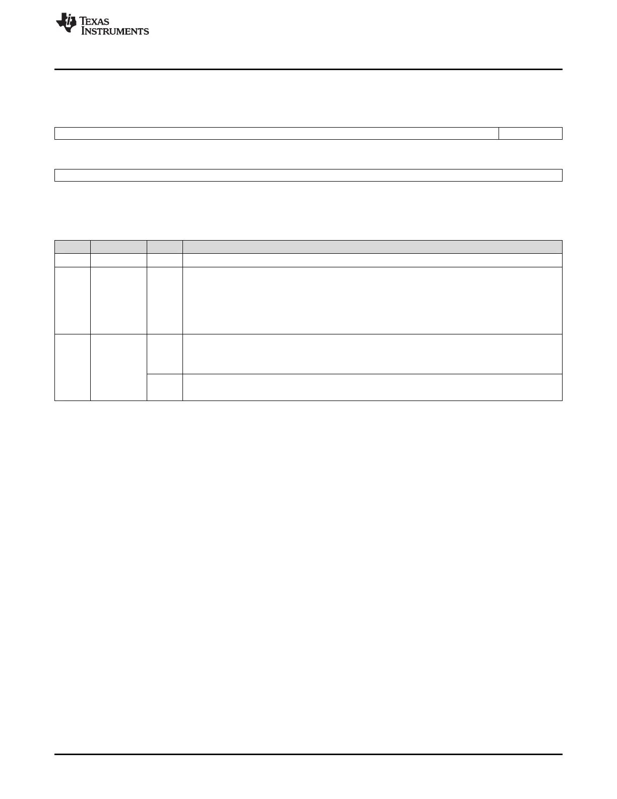
24.4.11 Interrupt Mapping Register (HTU INTMAP)
Figure 24-24. Interrupt Mapping Register (HTU INTMAP) [offset = 2Ch]
31 17 16
Reserved MAPSEL
R-0 R/WP-0
15 0
CPINTMAP
R/WP-0
LEGEND: R/W = Read/Write; R = Read only; WP = Write in privilege mode only; -n = value after reset
Table 24-23. Interrupt Mapping Register (HTU INTMAP) Field Descriptions
Bit Field Value Description
31-17 Reserved 0 Reads return 0. Writes have no effect.
16 MAPSEL Interrupt Mapping Select Bit
0 If MAPSEL is 0, then one bit of CPINTMAP selects one of two interrupt priorities 0 or 1 for the buffer
full interrupt for the according CP. The request lost and bus error interrupts of all CPs are set to
priority 0, independent of CPINTMAP.
1 If MAPSEL is 1, then one bit of CPINTMAP determines if the buffer full, request lost and bus error
interrupts of the according CP are assigned either to interrupt line 0 or to 1.
15-0 CPINTMAP CP Interrupt Mapping Bits
0 Interrupt of CP A (bit 2-x) of DCP x is mapped to interrupt line 0.
Interrupt of CP B (bit 2*x+1) of DCP x is mapped to interrupt line 0.
1 Interrupt of CP A (bit 2-x) of DCP x is mapped to interrupt line 1.
Interrupt of CP B (bit 2*x+1) of DCP x is mapped to interrupt line 1.

 Loading...


