Communication
Controller
Transfer Unit
FlexRay Module
base_TU
base_TU_RAM
base_CC
Register Set
Register Set
RAM
offset_CC
offset_TU
offset_TU_RAM
Overview
www.ti.com
1214
SPNU563A–March 2018
Submit Documentation Feedback
Copyright © 2018, Texas Instruments Incorporated
FlexRay Module
• Interrupt Control (INT)
The interrupt controller performs the following functions:
– Provides error and status interrupt flags
– Enable / disable interrupt sources
– Assignment of interrupt sources to the two module interrupt lines
– Enable / disable module interrupt lines
– Manages the two interrupt timers
– Stop watch time capturing
• 80-MHz Clock Signal
NOTE: VCLKA2 is used to provide the 80-MHz clock to the FlexRay Module. The second PLL /
Clock Source 6 in the microcontroller is typically used as source for VCLKA2.
Clock signal for the sample clock (SCLK) of the FlexRay module.
• Module Clock (VBUS
CLK
)
The FlexRay module clock (BCLK) is derived from the Peripheral Clock VBUS
CLK
of the microcontroller.
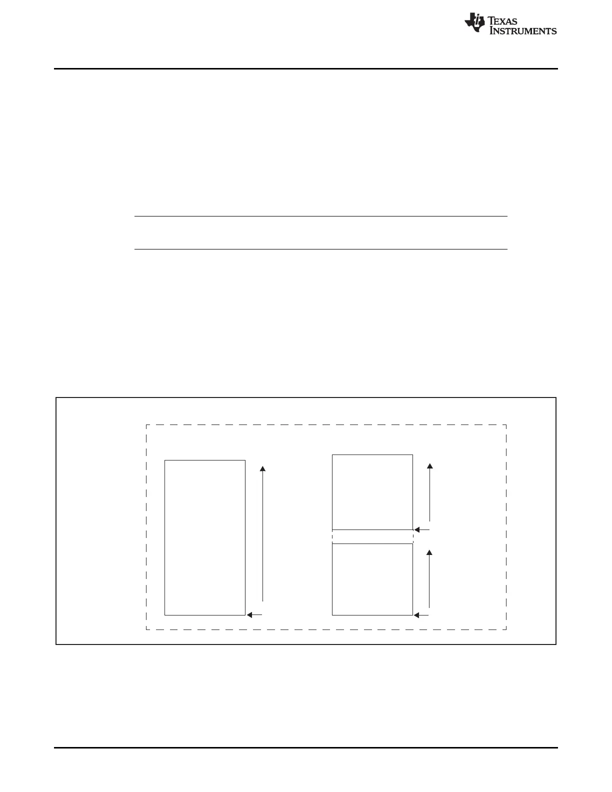
26.1.3 FlexRay Module Blocks
Figure 26-2 shows the different module blocks of the FlexRay module: the communication controller, the
transfer unit, and the transfer unit RAM. The RAM of the communication controller is only memory-
mapped in test mode, where it is mapped to the register set address range. The address ranges of the
three FlexRay blocks are shown in Table 26-1.
Figure 26-2. FlexRay Module Blocks

 Loading...


