IOMM Registers
www.ti.com
334
SPNU563A–March 2018
Submit Documentation Feedback
Copyright © 2018, Texas Instruments Incorporated
I/O Multiplexing and Control Module (IOMM)
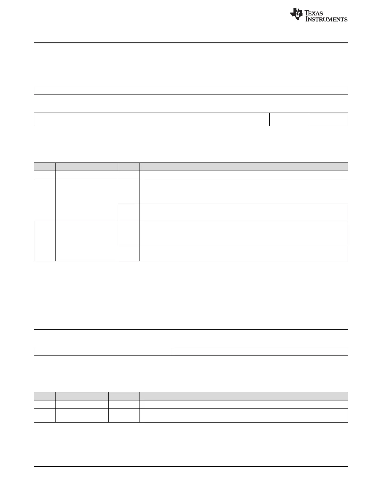
6.7.8 ERR_ENABLE_CLR_REG: Error Signaling Enable Clear Register
This register shows the error signaling enable status and allows disabling of the error signaling.
Figure 6-17. ERR_ENABLE_CLR_REG: Error Signaling Enable Clear Register (Offset = ECh)
31 8
Reserved
R-0
7 2 1 0
Reserved ADDR_ERR_
EN_CLR
PROT_ERR_
EN_CLR
R-0 R/WP-0 R/WP-0
LEGEND: R/W = Read/Write; R = Read only; WP = Write in privileged mode only; -n = value after reset
Table 6-20. Interrupt Enable Clear Register Field Descriptions
Bit Field Value Description
31-2 Reserved 0 Reads return 0, writes have no effect.
1 ADDR_ERR_EN_CLR Addressing Error Signaling Enable Clear
0 Read: Addressing Error signaling is disabled.
Write: Writing 0 has no effect.
1 Read: Addressing Error signaling is enabled.
Write: Addressing Error signaling is disabled.
0 PROT_ERR_EN_CLR Protection Error Signaling Enable Clear
0 Read: Protection Error signaling is disabled.
Write: Writing 0 has no effect.
1 Read: Protection Error signaling is enabled.
Write: Protection Error signaling is disabled.
6.7.9 FAULT_ADDRESS_REG: Fault Address Register
This register holds the address offset of the first fault transfer.
Figure 6-18. FAULT_ADDRESS_REG: Fault Address Register (Offset = F4h)
31 16
Reserved
R-0
15 9 8 0
Reserved FAULT_ADDR
R-0 R/WP-0
LEGEND: R/W = Read/Write; R = Read only; WP = Write in privileged mode only; -n = value after reset
Table 6-21. Fault Address Register Field Descriptions
Bit Field Value Description
31-9 Reserved 0 Reads return 0, writes have no effect.
8-0 FAULT_ADDR Fault Address. The fault address offset in case of an address error or a protection error
condition.

 Loading...


