RTI Control Registers
www.ti.com
596
SPNU563A–March 2018
Submit Documentation Feedback
Copyright © 2018, Texas Instruments Incorporated
Real-Time Interrupt (RTI) Module
NOTE: Writes to Reserved registers may clear the pending RTI interrupt.
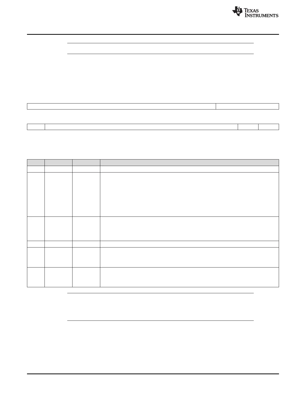
17.3.1 RTI Global Control Register (RTIGCTRL)
The global control register starts/stops the counters and selects the signal compared with the timebase
control circuit. This register is shown in Figure 17-12 and described in Table 17-2.
Figure 17-12. RTI Global Control Register (RTIGCTRL) [offset = 00]
31 20 19 16
Reserved NTUSEL
R-0 R/WP-0
15 14 2 1 0
COS Reserved CNT1EN CNT0EN
R/WP-0 R-0 R/WP-0 R/WP-0
LEGEND: R/W = Read/Write; R = Read only; WP = Write in privileged mode only; -n = value after reset
Table 17-2. RTI Global Control Register (RTIGCTRL) Field Descriptions
Bit Field Value Description
31-20 Reserved 0 Reads return 0. Writes have no effect.
19-16 NTUSEL Select NTU signal. These bits determine which NTU input signal is used as external timebase
0h NTU0
5h NTU1
Ah NTU2
Fh NTU3
All other
values
Tied to 0
15 COS Continue on suspend. This bit determines if both counters are stopped when the device goes into
halting debug mode or if they continue counting.
0 Counters are stopped while in halting debug mode.
1 Counters are running while in halting debug mode.
14-2 Reserved 0 Reads return 0. Writes have no effect.
1 CNT1EN Counter 1 enable. This bit starts and stops counter block 1 (RTIUC1 and RTIFRC1).
0 Counter block 1 is stopped.
1 Counter block 1 is running.
0 CNT0EN Counter 0 enable. This bit starts and stops counter block 0 (RTIUC0 and RTIFRC0).
0 Counter block 0 is stopped.
1 Counter block 0 is running.
NOTE: If the application uses the timebase circuit for synchronization between the communications
controller and the operating system and the device enters halting debug mode, the
synchronization may be lost depending on the COS setting in the RTI module and the halting
debug mode behavior of the communications controller.