www.ti.com
Module Operation
715
SPNU563A–March 2018
Submit Documentation Feedback
Copyright © 2018, Texas Instruments Incorporated
Direct Memory Access Controller (DMA) Module
20.2.12 FIFO Buffer
DMA FIFO is 4 levels deep and 64-bit wide (can hold up to 4 × 64-bits of data). They are used for Data
packing and unpacking.
The DMA FIFO has two states:
• EMPTY: The FIFO contains no data.
• FULL: The FIFO is filled or the element count has reached zero; the read operation has to be stopped.
DMA channels can only be switched when the FIFO is empty. This also implies that arbitration between
channels is done when the FIFO is empty.
The DMA has two FIFOs, FIFO A and FIFO B, each executing a channel that provides the capability to
execute a maximum of two channels concurrently.
The FIFO buffer may be bypassed through the use of the bypass feature in the port control register; see
Port Control Register (Section 20.3.1.51) for register details. Writing 1 to this bit limits the FIFO depth to
the size of one element. That means if the read element size is equal to or larger than the write element
size, after one element is read the write out to the destination starts. Otherwise, the write out to the
destination starts after enough reads have completed to do one write of the write element size. This
feature is particularly useful to minimize switching latency in-between channels. When bypass mode is
enabled, the DMA performs minimal transfers within an arbitration boundary. In addition, the bypass
feature allows arbitration between channels that can be carried out at a source element granularity.
However, it has to be considered that while in bypass mode, the DMA controller does not make optimal
use of the bus bandwidth. Since the read and write element sizes can be different, then the number of
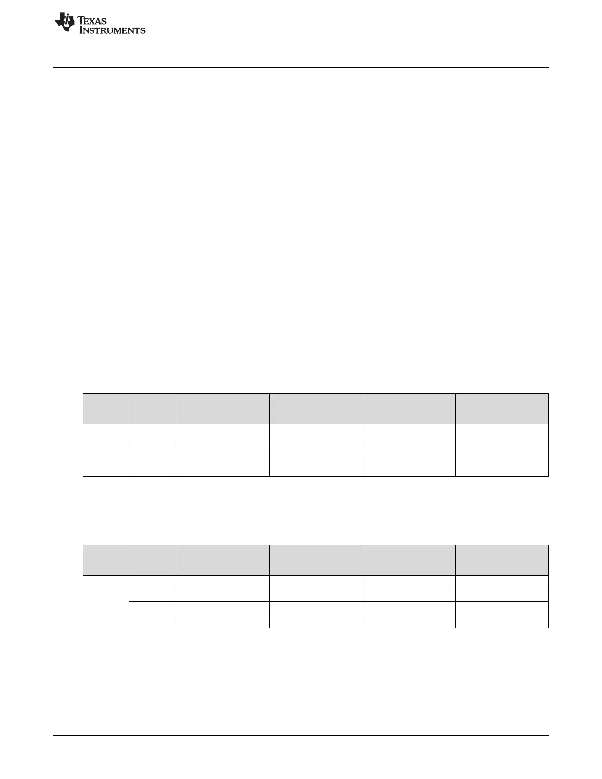
read and write transactions will be different. Table 20-4 and Table 20-5 show a comparison between the
number of read and write transactions performed by the DMA controller from one channel to another
before arbitration in non-bypass and bypass mode.
Table 20-4. Maximum Number of DMA Transactions per Channel in Non-Bypass Mode
Write
Element
Size
8 bit 16 bit 32 bit 64 bit
Read
Element
Size
8 bit 4 read 4 write 4 read 2 write 4 read 1 write 8 read 1 write
16 bit 2 read 4 write 4 read 4 write 4 read 2 write 4 read 1 write
32 bit 1 read 4 write 2 read 4 write 4 read 4 write 4 read 2 write
64 bit 1 read 8 write 1 read 4 write 2 read 4 write 4 read 4 write
Table 20-5. Maximum Number of DMA Transactions per Channel in Bypass Mode
Write
Element
Size
8 bit 16 bit 32 bit 64 bit
Read
Element
Size
8 bit 1 read 1 write 2 read 1 write 4 read 1 write 8 read 1 write
16 bit 1 read 2 write 1 read 1 write 2 read 1 write 4 read 1 write
32 bit 1 read 4 write 1 read 2 write 1 read 1 write 2 read 1 write
64 bit 1 read 8 write 1 read 4 write 1 read 2 write 1 read 1 write

 Loading...


