PBIST Control Registers
www.ti.com
414
SPNU563A–March 2018
Submit Documentation Feedback
Copyright © 2018, Texas Instruments Incorporated
Programmable Built-In Self-Test (PBIST) Module
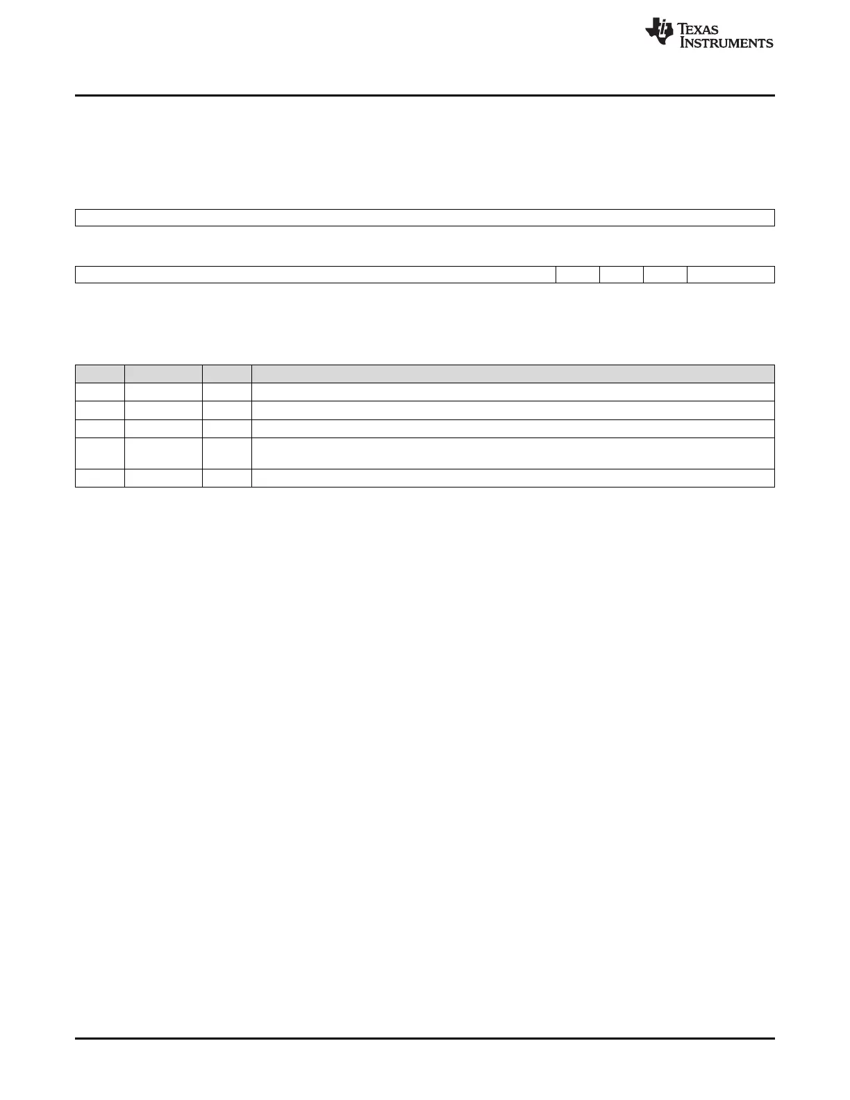
9.5.2 Datalogger Register (DLR)
This register puts the PBIST controller into the appropriate comparison modes for data logging. Figure 9-4
and Table 9-3 illustrate this register.
Figure 9-4. Datalogger Register (DLR) [offset = 0164h]
31 16
Reserved
R-0
15 5 4 3 2 1 0
Reserved DLR4 Rsvd DLR2 Reserved
R-0 R/W-0 R/W-1 R/W-0 R/W-0
LEGEND: R/W = Read/Write; R = Read only; -n = value after reset
Table 9-3. Datalogger Register (DLR) Field Descriptions
Bit Field Value Description
31-5 Reserved 0 Reads return 0. Do not change these bits from their default value.
4 DLR4 Config access: setting this bit allows the host processor to configure the PBIST controller registers.
3 Reserved 1 Do not change this bit from its default value of 1.
2 DLR2 ROM-based testing: setting this bit enables the PBIST controller to execute test algorithms that are
stored in the PBIST ROM.
1-0 Reserved 00 Do not change these bits from their default value of 00.
• DLR2: ROM-based testing mode
Writing a 1 to this register starts the ROM-based testing. This register is used to initiate ROM-based
testing from Config and ATE interfaces. Also, since a 1 in this bit position means the instruction ROM is
used for memory testing, all the intermediate interrupts and PBIST done signal after each memory test are
masked until all the selected algorithms in the ROM are executed for all RAM groups. However, a failure
would stop the test and report the status immediately.
• DLR4: Config access mode
This mode, when set, indicates the CPU is being used to access PBIST.

 Loading...


