Memory
Configurations,
Algorithms,
Backgrouns
Host CPU
Control Interface
System
and
Peripheral
Memories
Data Logger
PBIST
Controller
Memory
Data
Path
PBIST
ROM
Overview
www.ti.com
406
SPNU563A–March 2018
Submit Documentation Feedback
Copyright © 2018, Texas Instruments Incorporated
Programmable Built-In Self-Test (PBIST) Module
9.1 Overview
The PBIST (Programmable Built-In Self-Test) controller architecture provides a run-time-programmable
memory BIST engine for varying levels of coverage across many embedded memory instances.
9.1.1 Features of PBIST
• Information regarding on-chip memories, memory groupings, memory background patterns and test
algorithms stored in dedicated on-chip PBIST ROM
• Host processor interface to configure and start BIST of memories
• Supports testing of PBIST ROM itself as well
• Supports testing of each memory at its maximum access speed in application
• Implements intelligent clock gating to conserve power
• Execution of microcode from PBIST ROM supported for ROM clock speeds up to 100 MHz
9.1.2 PBIST vs. Application Software-Based Testing
The PBIST architecture consists of a small coprocessor with a dedicated instruction set targeted
specifically toward testing memories. This coprocessor executes test routines stored in the PBIST ROM
and runs them on multiple on-chip memory instances. The on-chip memory configuration information is
also stored in the PBIST ROM.
The PBIST Controller architecture offers significant advantages over tests running on the main Cortex-
R5F processor (application software-based testing):
• Embedded CPUs have a long access path to memories outside the tightly-couple memory sub-system,
while the PBIST controller has a dedicated path to the memories specifically for the self-test
• Embedded CPUs are designed for their targeted use and are often not easily programmed for memory
test algorithms.
• The memory test algorithm code on embedded CPUs is typically significantly larger than that needed
for PBIST.
• The embedded CPU is significantly larger than the PBIST controller.
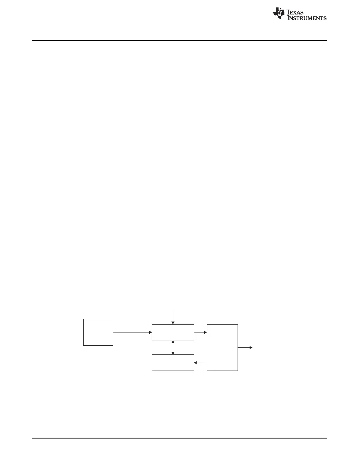
9.1.3 PBIST Block Diagram
Figure 9-1 illustrates the basic PBIST blocks and its wrapper logic for the device.
Figure 9-1. PBIST Block Diagram

 Loading...


