INT_
REQ0
INT_
REQ1
INT_
REQ2
INT_
REQ126
CHAN2
7
CHANMAP2[6:0]
INT_
REQ0
INT_
REQ1
INT_
REQ2
INT_
REQ126
CHAN126
7
CHANMAP126[6:0]
CHANNEL
MAPPING
127 Interrupt
Channels
NOTE:
CHAN0 and CHAN1 are hard wired to
INT_REQ0 and INT_REQ1, can NOT
be remapped.
www.ti.com
Interrupt Handling Inside VIM
669
SPNU563A–March 2018
Submit Documentation Feedback
Copyright © 2018, Texas Instruments Incorporated
Vectored Interrupt Manager (VIM) Module
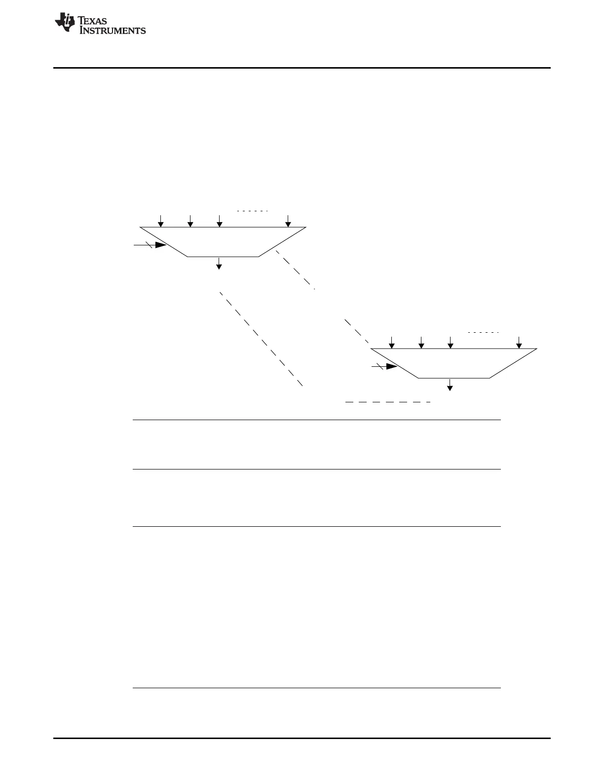
19.4.1 VIM Interrupt Channel Mapping
The VIM support 128 interrupt channels (including phantom interrupt). A block diagram of the VIM
interrupt requests arrangement from peripheral modules to the interrupt channels is provided in Figure 19-
4. Each interrupt channel (CHANx) has a corresponding mapping register bit field (CHANMAPx[6:0]). This
mapping register determines which interrupt channel it maps each VIM interrupt request. With this
scheme, the same request can be mapped to multiple channels. A lower numbered channel in each FIQ
and IRQ has higher priority. The programmability of the VIM allows software to control the interrupt
priority.
Figure 19-4. VIM Channel Mapping
NOTE: CHAN127
CHAN127 has no dedicated interrupt vector table entry. Therefore, CHAN127 shall NOT be
remapped to other INT_REQ (INT_REQ127 is reserved at device level).
In the reset state, the VIM maps all of the interrupt requests in the system to their respective interrupt
channels. Figure 19-5 shows the default state following the reset.
Figure 19-6 shows the VIM INT2 is remapped to both Channel 2 and 4, and INT3 is mapped to channel 3.
NOTE: By mapping INT2 to channel 2 and channel 4, and mapping INT3 to channel 3, it is possible
for the software to change the priority dynamically by changing the ENABLE register
(REQENASET and REQENACLR). When channel 2 is enabled, the priority is:
1. INT0
2. INT1
3. INT2
4. INT3
Disabling channel 2, the priority becomes:
1. INT0
2. INT1
3. INT3
4. INT2

 Loading...


