crystal
load
capacitors
OSCOUT
OSCIN
KELVIN_GND
OSCILLATOR
Oscillator
www.ti.com
520
SPNU563A–March 2018
Submit Documentation Feedback
Copyright © 2018, Texas Instruments Incorporated
Oscillator and PLL
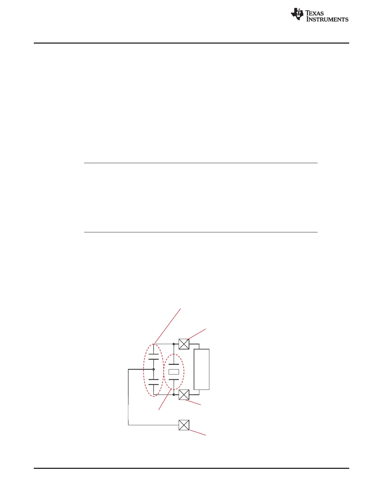
14.3 Oscillator
The clock generation path through the PLL begins with the oscillator. The oscillator consists of three
separate pads -- OSCIN, OSCOUT, and Kelvin_GND (see Figure 14-2).
The oscillator is responsible for two independent functions:
1. The oscillator is responsible for generating positive feedback in the external crystal/resonator with
appropriate load and tank circuitry. At start-up, the oscillator amplifies random noise. The external
circuitry acts like a band-pass and selects the crystal/resonator frequency to provide as positive
feedback into the amplifier. The positive feedback increases the amplitude of the output waveform into
the crystal/resonator (and the load circuitry), and the voltage waveform shows an envelope of
increasing amplitude. The oscillator can drive a crystal frequency that is within the data sheet range
t
c(OSC)
.
Looking at the input waveform into OSCIN, the voltage waveform is an AC-coupled, filtered version of
the OSCOUT waveform. The band-pass functionality of the crystal/resonator removes distortion from
the OSCOUT waveform, leaving a sinusoidal input waveform.
NOTE: Vendor Validation of Resonators/Crystals
The crystal is a very tight bandpass filter while a resonator is a somewhat wider bandpass.
The load circuitry pulls the center frequency of the bandpass.
Texas Instruments strongly encourages each customer to submit samples of the device to
the resonator/crystal vendor for validation. The vendor is equipped to determine what load
capacitances will best tune their resonator/crystal to the microcontroller device for optimum
start-up and operation over temperature and voltage extremes. The vendor also factors in
margins for variations in the microcontroller process.
2. The oscillator is also responsible for squaring-up the input waveform. This squaring-up converts the
sinusoid into a square wave at the core logic levels. The input path limits the input frequency range as
a low-pass filter with a cutoff frequency.
The oscillator has a frequency range that is determined by the driving capability of external
crystals/resonators (feedback path). If a clock is driven directly into the oscillator, then the feedback
path is not relevant and the frequency range is determined solely by the forward path (which typically
allows a higher frequency); the device can support inputs within the data sheet range t
c(OSC_Sqr)
.
Figure 14-2. Clock Generation Path

 Loading...


