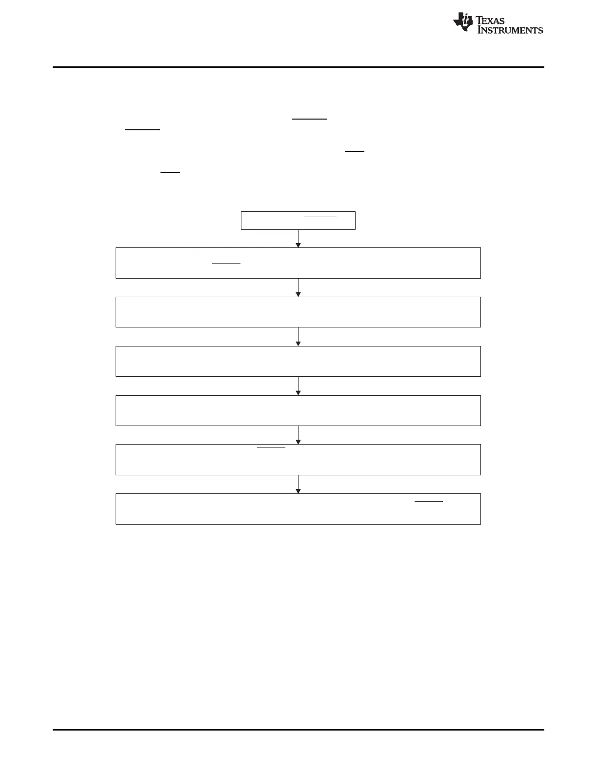
Initialize VIM RAM. Map the ESM low priority interrupt service routine and high priority interrupt
service routine to pre-defined device specific interrupt channel. (Refer to device specific datasheet.)
Force error on pin to check the functionality of pin and external monitoring
device connected to pin (ESMEKR).
ERROR ERROR
ERROR
Power up or PORRST
Enable the interrupt in VIM and CPU.
Map ESM interrupt to high/low (ESM Group1 only, see register
ESMILSR1 and ESMILCR1, ESMILSR4 and ESMILCR4, ESMILSR7 and ESMILCR7).
Define ESM Low-Time Counter Preload Register ESMLTCPR to determine the pin
low time in case an error occurs.
ERROR
Enable ESM interrupt and influence on pin (ESM Group1 only, see register ESMIEPSR1,
ESMIEPCR1, ESMIESR1, and ESMIECR1; ESMIEPSR4, ESMIEPCR4, ESMIESR4, and ESMIECR4;
ESMIEPSR7, ESMIEPCR7, ESMIESR7, and ESMIECR7).
ERROR
Recommended Programming Procedure
www.ti.com
564
SPNU563A–March 2018
Submit Documentation Feedback
Copyright © 2018, Texas Instruments Incorporated
Error Signaling Module (ESM)
16.3 Recommended Programming Procedure
During the initialization stage, the application code should follow the recommendations in Figure 16-10 to
initialize the ESM.
Once an error occurs, it can trigger an interrupt, ERROR pin outputs low depending on the ESM settings.
Once the ERROR pin outputs low, a power on reset or a write of 0x5 to ESMEKR is required to release
the ESM back to normal state. The application can read the error status registers (ESMSR1, ESMSR4,
ESMSR7, ESMSR2, and ESMSR3) to debug the error. If an RST is triggered or the error interrupt has
been served, the error flag of Group2 should be read from ESMSSR2 because the error flag in ESMSR2
will be cleared by RST.
Figure 16-10. ESM Initialization

 Loading...


