www.ti.com
IOMM Registers
333
SPNU563A–March 2018
Submit Documentation Feedback
Copyright © 2018, Texas Instruments Incorporated
I/O Multiplexing and Control Module (IOMM)
6.7.7 ERR_ENABLE_REG: Error Signaling Enable Register
This register shows the interrupt enable status and allows enabling of the interrupts.
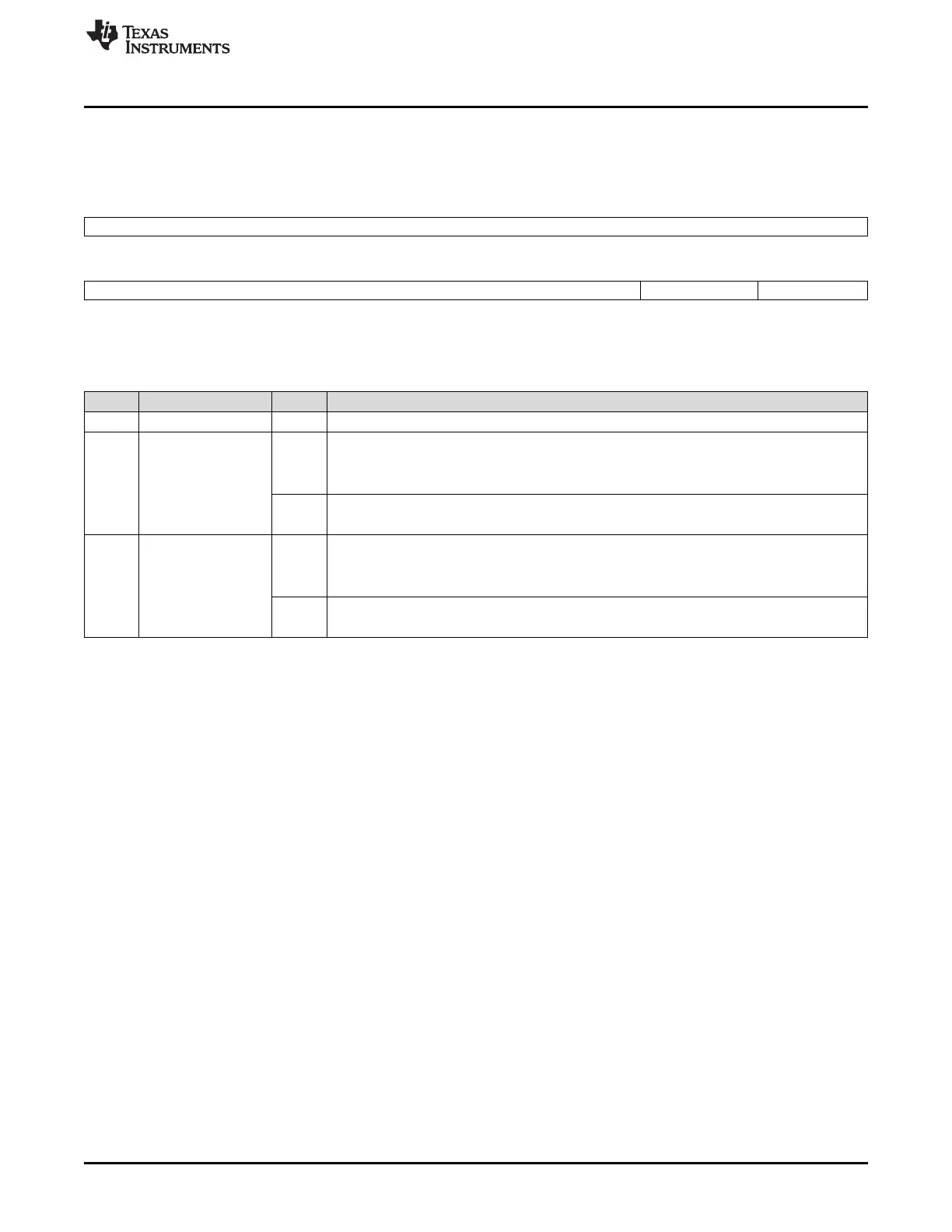
Figure 6-16. ERR_ENABLE_REG: Error Signaling Enable Register (Offset = E8h)
31 8
Reserved
R-0
7 2 1 0
Reserved ADDR_ERR_EN PROT_ERR_EN
R-0 R/WP-0 R/WP-0
LEGEND: R/W = Read/Write; R = Read only; WP = Write in privileged mode only; -n = value after reset
Table 6-19. Error Enable Register Field Descriptions
Bit Field Value Description
31-2 Reserved 0 Reads return 0, writes have no effect.
1 ADDR_ERR_EN Addressing Error Signaling Enable
0 Read: Addressing Error Signaling is disabled.
Write: Writing 0 has no effect.
1 Read: Addressing Error Signaling is enabled.
Write: Addressing Error Signaling is enabled.
0 PROT_ERR_EN Protection Error Signaling Enable
0 Read: Protection Error Signaling is disabled.
Write: Writing 0 has no effect.
1 Read: Protection Error Signaling is enabled.
Write: Protection Error Signaling is enabled.

 Loading...


