DCAN Control Registers
www.ti.com
1492
SPNU563A–March 2018
Submit Documentation Feedback
Copyright © 2018, Texas Instruments Incorporated
Controller Area Network (DCAN) Module
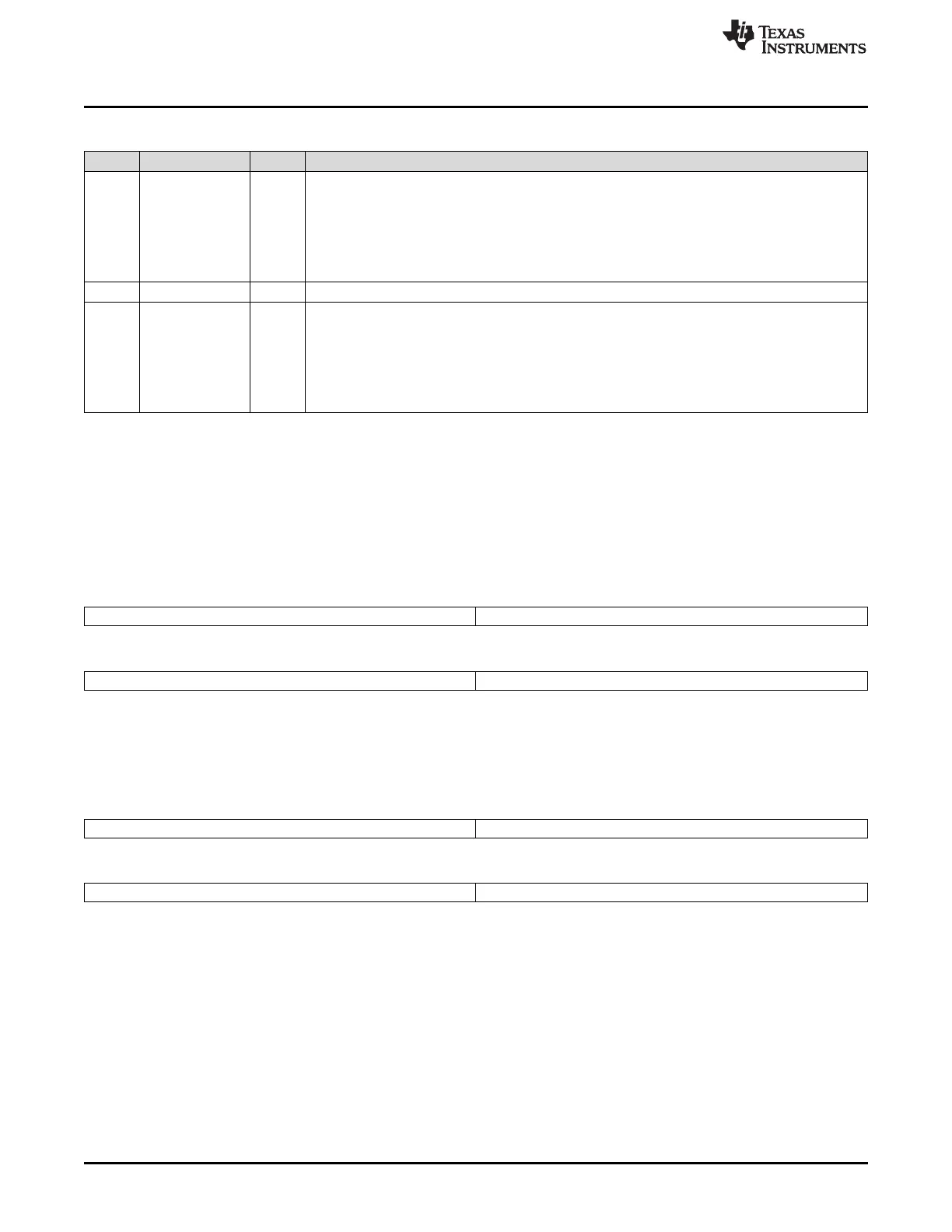
Table 27-32. IF3 Message Control Register (DCAN IF3MCTL) Field Descriptions (continued)
Bit Field Value Description
7 EoB End of Block
0 The message object is part of a FIFO Buffer block and is not the last message object of the FIFO
Buffer block.
1 The message object is a single message object or the last message object in a FIFO Buffer block.
Note: This bit is used to concatenate multiple message objects to build a FIFO Buffer. For single
message objects (not belonging to a FIFO Buffer), this bit must always be set to 1.
6-4 Reserved 0 These bits are always read as 0. Writes have no effect.
3-0 DLC Data Length Code
0-8h Data Frame has 0-8 data bits.
9h-Fh Data Frame has 8 data bytes.
Note: The Data Length Code of a message object must be defined the same as in all the
corresponding objects with the same identifier at other nodes. When the message handler stores a
data frame, it will write the DLC to the value given by the received message.
27.17.32 IF3 Data A and Data B Registers (DCAN IF3DATA/DATB)
The data bytes of CAN messages are stored in the IF3 registers in the following order.
In a CAN Data Frame, Data 0 is the first, and Data 7 is the last byte to be transmitted or received. In
CAN's serial bit stream, the MSB of each byte will be transmitted first.
Figure 27-73. IF3 Data A Register (DCAN IF3DATA) [offset = 150h]
31 24 23 16
Data 3 Data 2
R-0 R-0
15 8 7 0
Data 1 Data 0
R-0 R-0
LEGEND: R = Read; -n = value after reset
Figure 27-74. IF3 Data B Register (DCAN IF3DATB) [offset = 154h]
31 24 23 16
Data 7 Data 6
R/WP-0 R/WP-0
15 8 7 0
Data 5 Data 4
R-0 R-0
LEGEND: R = Read; -n = value after reset

 Loading...


