www.ti.com
ADC Registers
937
SPNU563A–March 2018
Submit Documentation Feedback
Copyright © 2018, Texas Instruments Incorporated
Analog To Digital Converter (ADC) Module
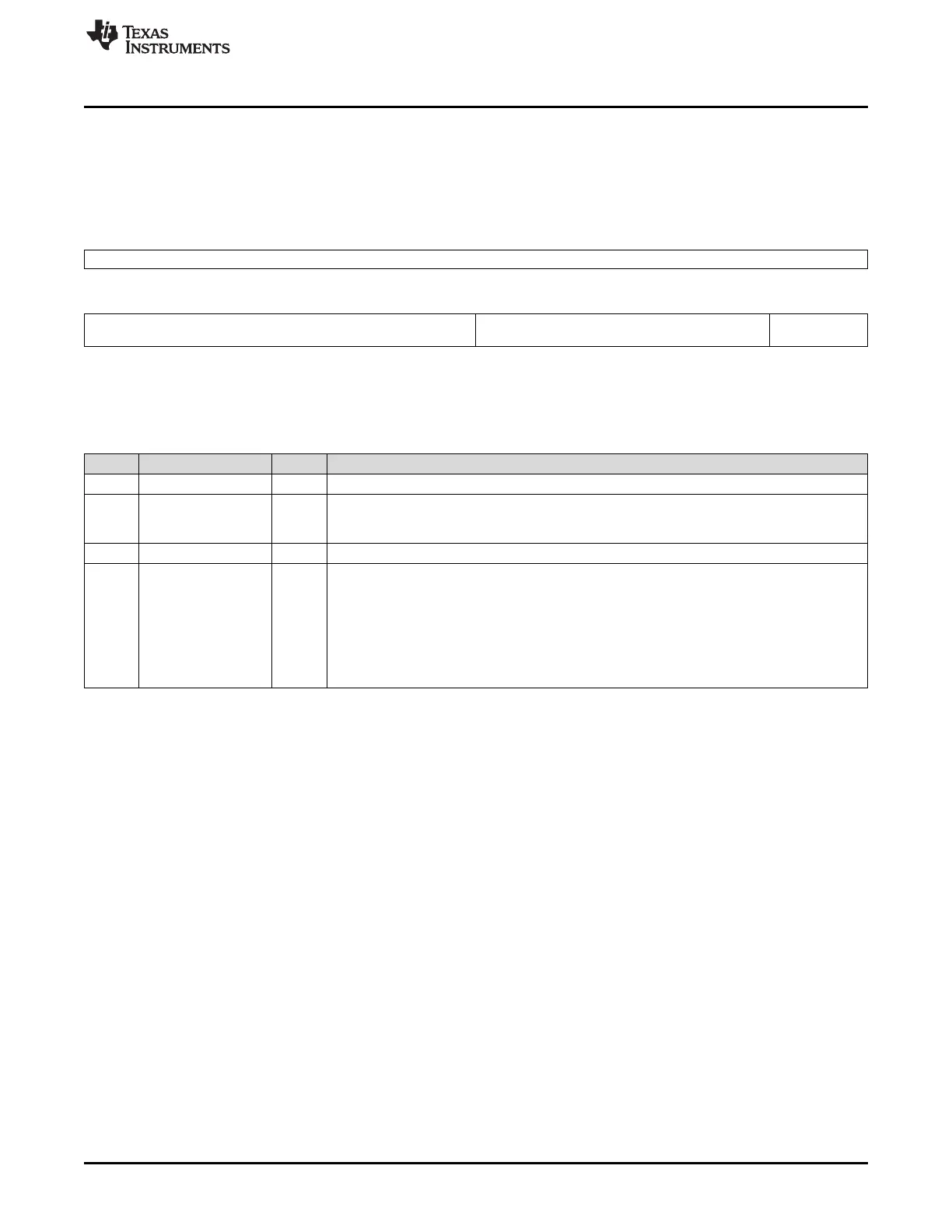
22.3.53 ADC Group2 Sample Cap Discharge Control Register (ADG2SAMPDISEN)
ADC Group2 Sample Cap Discharge Control Register (ADG2SAMPDISEN) is shown in Figure 22-82 and
described in Table 22-59.
Figure 22-82. ADC Group2 Sample Cap Discharge Control Register (ADG2SAMPDISEN)
[offset = 124h]
31 16
Reserved
R-0
15 8 7 1 0
G2_SAMP_DIS_CYC Reserved G2_SAMP_
DIS_EN
R/W-0 R-0 R/W-0
LEGEND: R/W = Read/Write; R = Read only; -n = value after reset
Table 22-59. ADC Group2 Sample Cap Discharge Control Register (ADG2SAMPDISEN)
Field Descriptions
Bit Field Value Description
31-16 Reserved 0 Reads return 0. Writes have no effect.
15-8 G2_SAMP_DIS_CYC Group2 sample cap discharge cycles. These bits specify the duration in terms of ADCLK cycles
for which the ADC internal sampling capacitor is allowed to discharge before sampling the input
channel voltage.
7-1 Reserved 0 Reads return 0. Writes have no effect.
0 G2_SAMP_DIS_EN Group2 sample cap discharge enable.
Any operation mode read/write:
0 Group2 sample cap discharge mode is disabled.
1 Group2 sample cap discharge mode is enabled. The ADC internal sampling capacitor is
connected to the V
REFLO
reference voltage for a duration specified by the G2_SAMP_DIS_CYC
field. After this discharge time has expired the selected ADC input channel is sampled and
converted normally based on the Group2 settings.

 Loading...


