EMIF Registers
www.ti.com
832
SPNU563A–March 2018
Submit Documentation Feedback
Copyright © 2018, Texas Instruments Incorporated
External Memory Interface (EMIF)
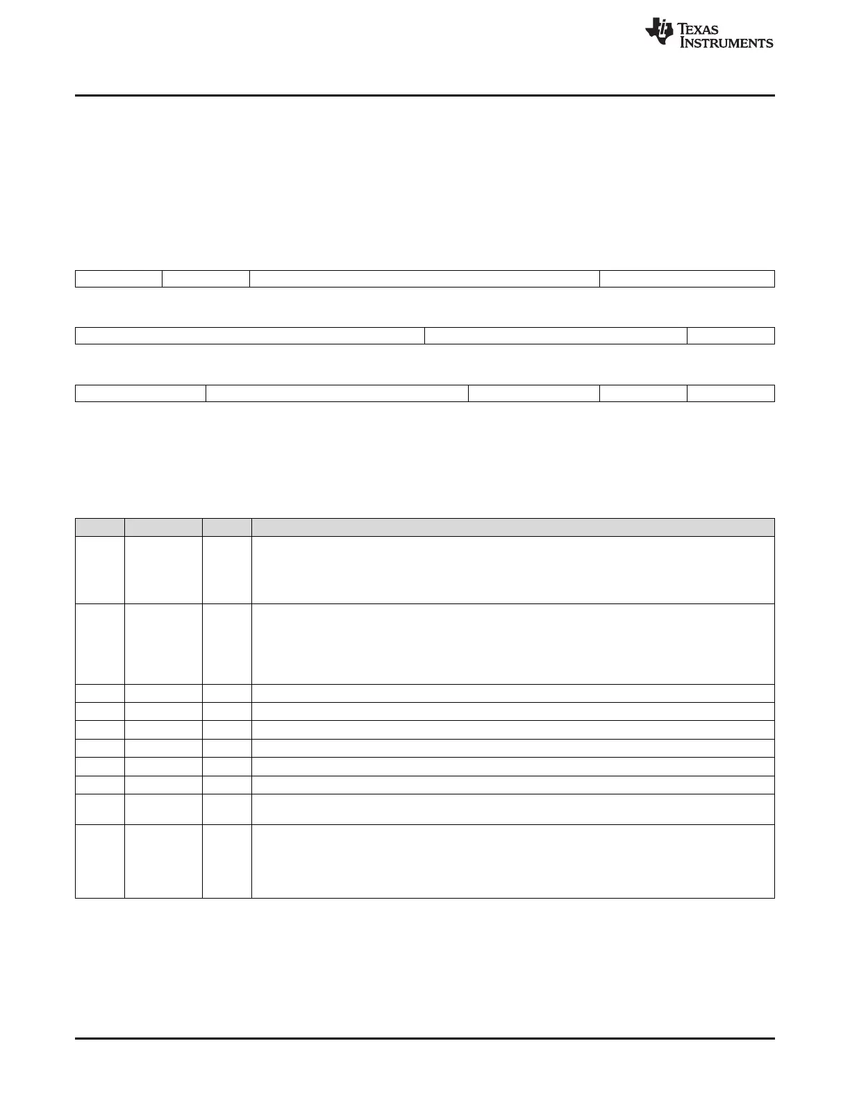
21.3.5 Asynchronous n Configuration Registers (CE2CFG-CE5CFG)
The asynchronous n configuration registers (CE2CFG, CE3CFG, CE4CFG, and CE5CFG) are used to
configure the shaping of the address and control signals during an access to asynchronous memory
connected to CS2, CS3, CS4, and CS5, respectively. CS5 is not available on this device. It is also used to
program the width of asynchronous interface and to select from various modes of operation. This register
can be written prior to any transfer, and any asynchronous transfer following the write will use the new
configuration. The CEnCFG is shown in Figure 21-19 and described in Table 21-29.
Figure 21-19. Asynchronous n Configuration Register (CEnCFG) [offset = 10h - 1Ch]
31 30 29 26 25 24
SS EW
(A)
W_SETUP W_STROBE
(B)
R/W-0 R/W-0 R/W-Fh R/W-3Fh
23 20 19 17 16
W_STROBE
(B)
W_HOLD R_SETUP
R/W-3Fh R/W-7h R/W-Fh
15 13 12 7 6 4 3 2 1 0
R_SETUP R_STROBE
(B)
R_HOLD TA ASIZE
R/W-Fh R/W-3Fh R/W-7h R/W-3h R/W-0
LEGEND: R/W = Read/Write; R = Read only; -n = value after reset
A. The EW bit must be cleared to 0.
B. This bit field must be cleared to 0 if the EMIF on your device does not have an EMIF_nWAIT pin.
Table 21-29. Asynchronous n Configuration Register (CEnCFG) Field Descriptions
Bit Field Value Description
31 SS Select Strobe bit. This bit defines whether the asynchronous interface operates in Normal Mode or
Select Strobe Mode. See Section 21.2.6 for details on the two modes of operation.
0 Normal Mode enabled.
1 Select Strobe Mode enabled.
30 EW Extend Wait bit. This bit defines whether extended wait cycles will be enabled. See Section 21.2.6.6 on
extended wait cycles for details. This bit field must be set to 0, if the EMIF on your device does not have
an EMIF_nWAIT pin.
0 Extended wait cycles disabled.
1 Extended wait cycles enabled.
29-26 W_SETUP 0-Fh Write setup width in EMIF_CLK cycles, minus one cycle. See Section 21.2.6.3 for details.
25-20 W_STROBE 0-3Fh Write strobe width in EMIF_CLK cycles, minus one cycle. See Section 21.2.6.3 for details.
19-17 W_HOLD 0-7h Write hold width in EMIF_CLK cycles, minus one cycle. See Section 21.2.6.3 for details.
16-13 R_SETUP 0-Fh Read setup width in EMIF_CLK cycles, minus one cycle. See Section 21.2.6.3 for details.
12-7 R_STROBE 0-3Fh Read strobe width in EMIF_CLK cycles, minus one cycle. See Section 21.2.6.3 for details.
6-4 R_HOLD 0-7h Read hold width in EMIF_CLK cycles, minus one cycle. See Section 21.2.6.3 for details.
3-2 TA 0-3h Minimum Turn-Around time. This field defines the minimum number of EMIF_CLK cycles between reads
and writes, minus one cycle. See Section 21.2.6.3 for details.
1-0 ASIZE Asynchronous Data Bus Width. This field defines the width of the asynchronous device's data bus.
0 8-bit data bus
1h 16-bit data bus
2h-3h Reserved

 Loading...


