AD1IN31
AD1IN0
10/12-bit
Analog-to-Digital
Successive Approximation
Converter
Sequencer and
ADC Results’ Memory Interface
Controller
10/12-bit
VBUS Interface for Access to ADC Registers and Results’ RAM
AIN
V
C CA D
V
SS AD
End Of
Conversion
Result
R1 R2
S1 S2 S3 S4
S6
AD
REFHI
AD
REFLO
ADCLK
START
PDZ
Self Test
&
Calibration
Results’ RAM
AD1EXT_SEL[4:0]
AD1EXT_ENA
Sample Cap
Discharge Switch
Input “Multiplexer”
GP1_DMA_REQ
EV_DMA_REQ
GP2_INT
GP1_INT
EV_INT
MAG_THR_INT[5:0]
Analog Core Interface
Input
Channel
Selection
32
SWCNTRL[3:0]
Samp_Cap_Discharge
Interrupt
Generation
GP1_DMA_REQ
DMA
Generation
Request
ADEVSRC.EV_SRC[2:0],
ADG1SRC.G1_SRC[2:0],
and ADG2SRC.G2_SRC[2:0]
Event Trigger
Generation
ADC_res
ADC_res
www.ti.com
Overview
851
SPNU563A–March 2018
Submit Documentation Feedback
Copyright © 2018, Texas Instruments Incorporated
Analog To Digital Converter (ADC) Module
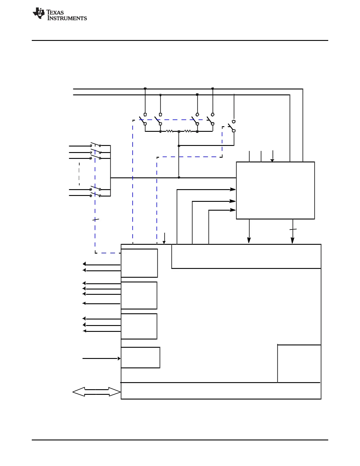
22.1.1 Introduction
This section presents a brief functional description of the analog-to-digital converter (ADC) module.
Figure 22-2 shows the components of the ADC module.
Figure 22-2. ADC Block Diagram

 Loading...


