www.ti.com
GIO Control Registers
1205
SPNU563A–March 2018
Submit Documentation Feedback
Copyright © 2018, Texas Instruments Incorporated
General-Purpose Input/Output (GIO) Module
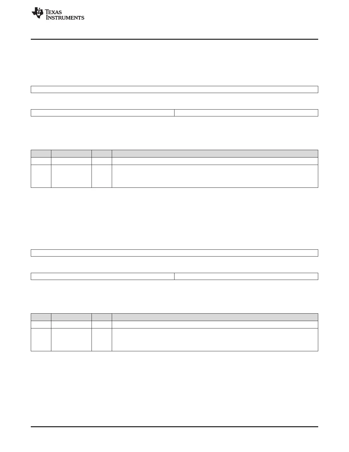
25.5.11 GIO Data Direction Registers (GIODIR[A-B])
The GIODIR register controls whether the pins of a given port are configured as inputs or outputs.
Figure 25-17 and Table 25-14 describe this register.
Figure 25-17. GIO Data Direction Registers (GIODIR[A-B]) [offset = 34h, 54h]
31 16
Reserved
R-0
15 8 7 0
Reserved GIODIR[7:0]
R-0 R/W-0
LEGEND: R/W = Read/Write; R = Read only; -n = value after reset
Table 25-14. GIO Data Direction Registers (GIODIR[A-B]) Field Descriptions
Bit Field Value Description
31-8 Reserved 0 Reads return 0. Writes have no effect.
7-0 GIODIR[n] GIO data direction of port n, pins [7:0]
0 The GIO pin is an input. Note: If the pin direction is set as an input, the output buffer is tristated.
1 The GIO pin is an output.
25.5.12 GIO Data Input Registers (GIODIN[A-B])
Values in the GIODIN register reflect the current state (high = 1 or low = 0) on the pins of the port.
Figure 25-18 and Table 25-15 describe this register.
Figure 25-18. GIO Data Input Registers (GIODIN[A-B]) [offset = 38h, 58h]
31 16
Reserved
R-0
15 8 7 0
Reserved GIODIN[7:0]
R-0 R/W-0
LEGEND: R/W = Read/Write; R = Read only; -n = value after reset
Table 25-15. GIO Data Input Registers (GIODIN[A-B]) Field Descriptions
Bit Field Value Description
31-8 Reserved 0 Reads return 0. Writes have no effect.
7-0 GIODIN[n] GIO data input for port n, pins [7:0]
0 The pin is at logic low (0).
1 The pin is at logic high (1).

 Loading...


