T1
T3
T4
T5
T8
T9
T6
T7
HW Reset
Power On
READYWAKEUP HALT
MONITOR
CONFIG
STARTUP
MODE
T10
T11
T12
T13
T14
T15
T17
T16
Transition triggered by host command
Transition triggered by internal conditions
Transition triggered by host command OR internal conditions
DEFAULT_
CONFIG
T2
NORMAL
ACTIVE
NORMAL
PASSIVE
www.ti.com
Module Operation
1231
SPNU563A–March 2018
Submit Documentation Feedback
Copyright © 2018, Texas Instruments Incorporated
FlexRay Module
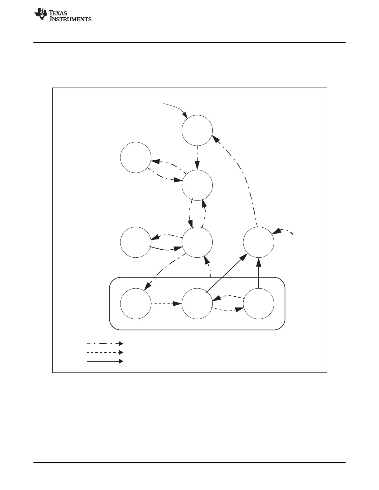
26.2.6 Communication Controller States
26.2.6.1 Communication Controller State Diagram
Figure 26-12. Overall State Diagram of Communication Controller
State transitions are controlled by the reset and FlexRay receive (rxd1, 2) pins, the POC state machine,
and by the CHI command vector SUCC1.CMD(3-0).
The Communication Controller exits from all states to HALT state after application of the FREEZE
command (SUCC1.CMD(3-0) = 0111b).

 Loading...


