1 6
)1]0...8[)(1]0...8[_( ++ S P R R A T EA M O U N TS P R
O u t p u t C L K
f
N F
N VN S
f ´´=D
2
N F
N VN S
D e p t h ´=
2
[ % ]
Modulation Period (1/f
s
)
Modulation
f
0
- n%
f
0
-2n%
f
0
Time (Ps)
Frequency (MHz)
Depth
www.ti.com
PLL
527
SPNU563A–March 2018
Submit Documentation Feedback
Copyright © 2018, Texas Instruments Incorporated
Oscillator and PLL
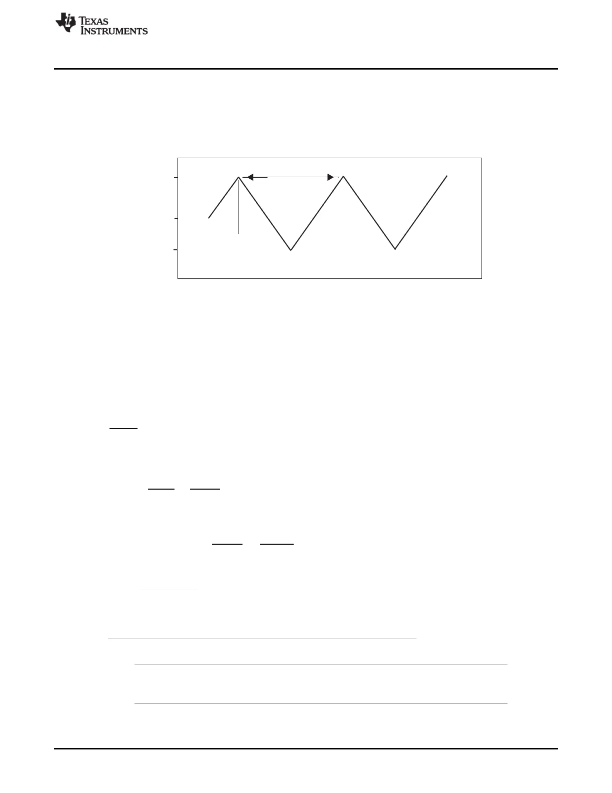
14.5.1 Modulation
Optionally, the frequency can be modulated, that is, a controlled jitter is introduced onto the baseline
frequency of the PLL. This modulation mechanism is not shown in Figure 14-4. When the PLL is used in
the modulating mode, the programmable modulation block varies the PLL frequency from the baseline
frequency (f
baseline
= (f
CLKIN
/NR) × NF/(OD × R)) to f
baseline
× (1 - 2 × Depth) in a period defined by 1/f
s
; the
modulation waveform is triangular and should be enabled after lock.
The modulation is digital and the spreading profile is triangular, down-spread which implies:
• the modulation waveform is composed of a series of frequency steps.
• the modulation frequency and modulation depth are both well controlled due to their digital character.
• the average frequency during modulation is lower than the average frequency prior to enabling
modulation. The depth of modulation, however, sets the new average frequency.
• the modulation frequency must be selected slower than the loop bandwidth. From a practical
perspective, NS should be near 20.
The modulation fields have a simple geometric meaning:
• the modulation step size is:
(8)
• the number of steps per modulation period is 2 × NS
• the modulation depth is given by:
(9)
• the modulation frequency is:
(10)
• MULMOD minimizes frequency offset when programmed as:
(11)
NOTE: Modulation should be enabled after Lock
Enable modulation after the lock is completed.

 Loading...


