2048
)1]0...8[_( +
=
A M O U N TS P R
N V
2 5 6
)2 5 6]0...8[]0...1 5[( ++
=
M U L M O DP L L M U L
N F
2 5 6
)2 5 6]0.. .1 5[( +
=
P L L M U L
N F
PLL
www.ti.com
526
SPNU563A–March 2018
Submit Documentation Feedback
Copyright © 2018, Texas Instruments Incorporated
Oscillator and PLL
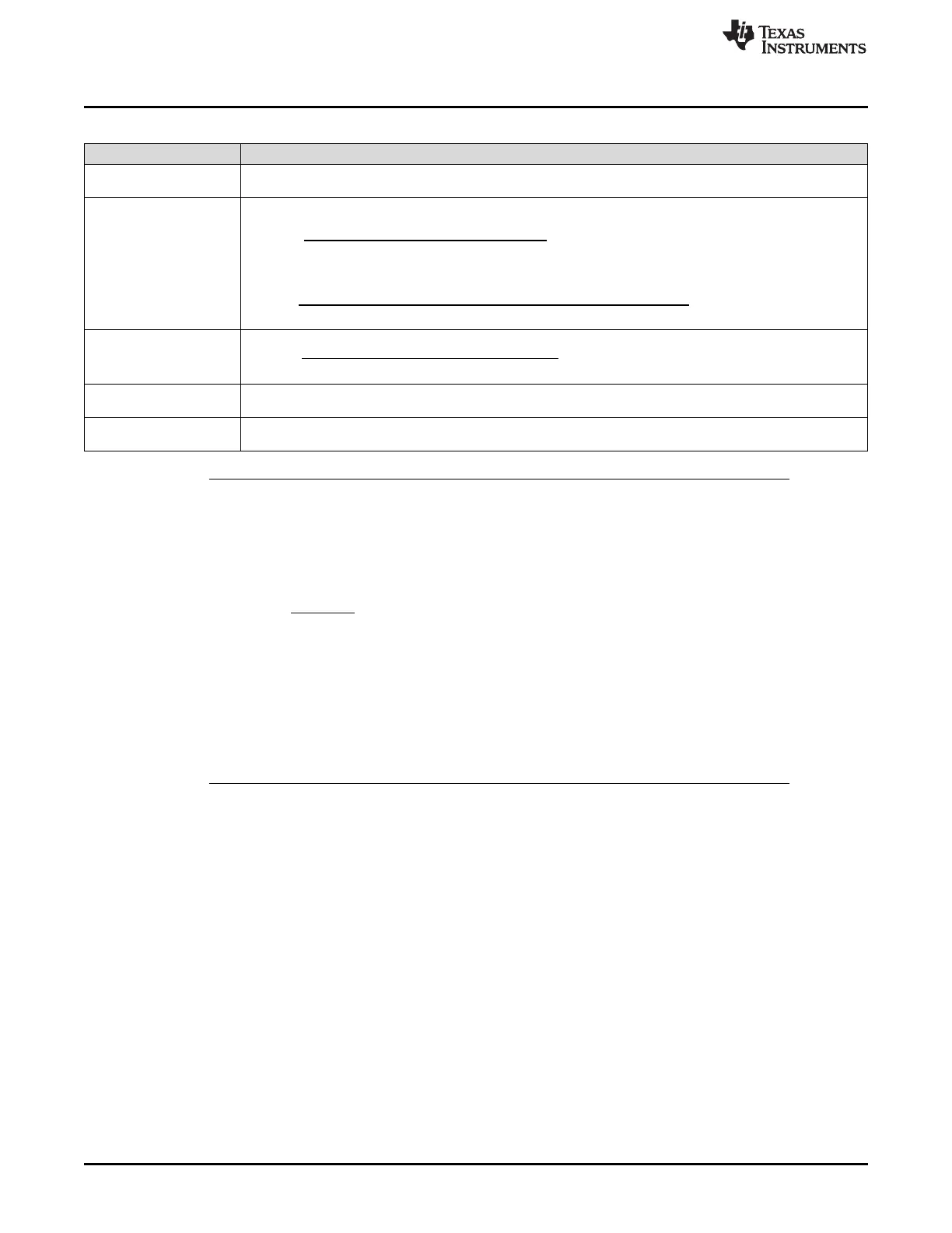
Table 14-2. PLL Value Encoding
PLL
NR
(2)
NF
Non-modulated:
(3)
Modulated:
(4)
NV
(5)
NS
(6)
OD
(7)
NOTE: ODPLL change should occur prior to enabling asynchronous clock domains
Since changing the ODPLL bit-field causes the PLL CLK to be gated, these changes to
ODPLL should be completed before configuring a clock domain for an asynchronous clock
source. Some clock domains (RTICLK1, VCLK2) require a frequency relationship to the
VCLK.
If the PLL is clocking VCLK and it is stopped for some cycles, then the frequency relationship
is temporarily violated.
Many asynchronous domains require frequency relationships between VCLK and the
asynchronous domain. Therefore, if the PLL clock is the source for GCLK1, HCLK, and
VCLK, then the gating produces a short-term change in the PLL clock frequency (and hence
also the VCLK frequency). As such, this frequency change could violate the requirements for
an asynchronous clock domain.

 Loading...


