Control Registers
www.ti.com
1540
SPNU563A–March 2018
Submit Documentation Feedback
Copyright © 2018, Texas Instruments Incorporated
Multi-Buffered Serial Peripheral Interface Module (MibSPI) with Parallel Pin
Option (MibSPIP)
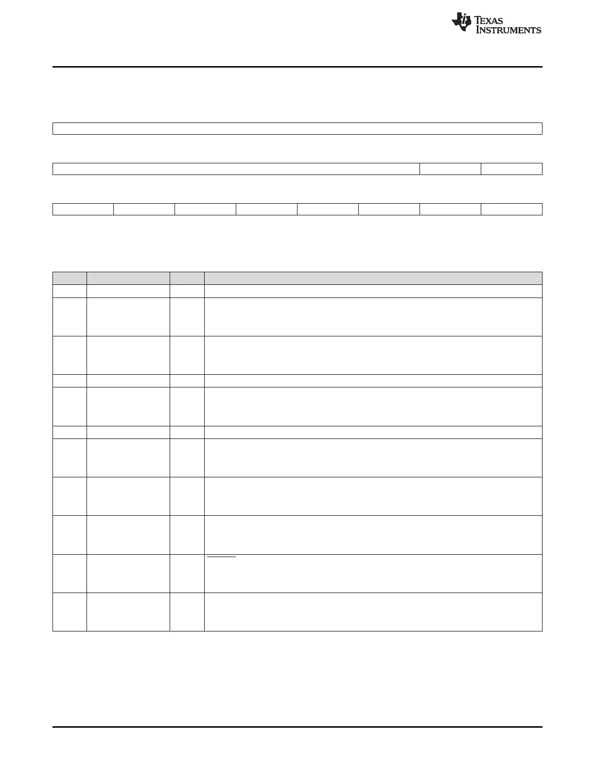
28.3.4 SPI Interrupt Level Register (SPILVL)
Figure 28-35. SPI Interrupt Level Register (SPILVL) [offset = 0Ch]
31 16
Reserved
R-0
15 10 9 8
Reserved TXINTLVL RXINTLVL
R-0 R/W-0 R/W-0
7 6 5 4 3 2 1 0
Reserved RXOVRNINTL Reserved BITERRLVL DESYNCLVL PARERRLVL TIMEOUTLVL DLENERRLVL
R-0 R/W-0 R-0 R/W-0 R/W-0 R/W-0 R/W-0 R/W-0
LEGEND: R/W = Read/Write; R = Read only; -n = value after reset
Table 28-12. SPI Interrupt Level Register (SPILVL) Field Descriptions
Bit Field Value Description
31-10 Reserved 0 Reads return 0. Writes have no effect.
9 TXINTLVL Transmit interrupt level.
0 Transmit interrupt is mapped to interrupt line INT0.
1 Transmit interrupt is mapped to interrupt line INT1.
8 RXINTLVL Receive interrupt level.
0 Receive interrupt is mapped to interrupt line INT0.
1 Receive interrupt is mapped to interrupt line INT1.
7 Reserved 0 Reads return 0. Writes have no effect.
6 RXOVRNINTLVL Receive overrun interrupt level.
0 Receive overrun interrupt is mapped to interrupt line INT0.
1 Receive overrun interrupt is mapped to interrupt line INT1.
5 Reserved 0 Reads return 0. Writes have no effect.
4 BITERRLVL Bit error interrupt level.
0 Bit error interrupt is mapped to interrupt line INT0.
1 Bit error interrupt is mapped to interrupt line INT1.
3 DESYNCLVL Desynchronized slave interrupt level. (master mode only).
0 An interrupt caused by desynchronization of the slave is mapped to interrupt line INT0.
1 An interrupt caused by desynchronization of the slave is mapped to interrupt line INT1.
2 PARERRLVL Parity error interrupt level.
0 A parity error interrupt is mapped to interrupt line INT0.
1 A parity error interrupt is mapped to interrupt line INT1.
1 TIMEOUTLVL SPIENA pin time-out interrupt level.
0 An interrupt on a time-out of the ENA signal (TIMEOUT = 1) is mapped to interrupt line INT0.
1 An interrupt on a time-out of the ENA signal (TIMEOUT = 1) is mapped to interrupt line INT1.
0 DLENERRLVL Data length error interrupt level (line) select.
0 An interrupt on data length error is mapped to interrupt line INT0.
1 An interrupt on data length error is mapped to interrupt line INT1.

 Loading...


