www.ti.com
PBIST Control Registers
413
SPNU563A–March 2018
Submit Documentation Feedback
Copyright © 2018, Texas Instruments Incorporated
Programmable Built-In Self-Test (PBIST) Module
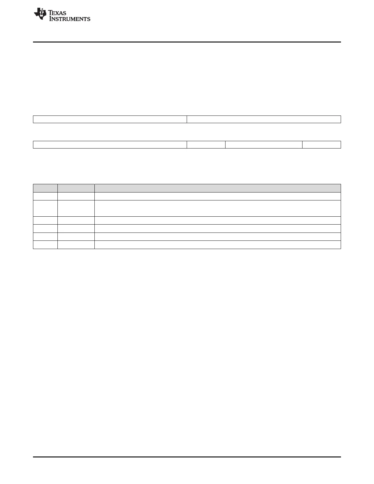
9.5.1 RAM Configuration Register (RAMT)
This register is divided into following internal registers, none of which have a default value after reset.
Figure 9-3 and Table 9-2 illustrate this register.
This register provides the information regarding the memory being currently tested. In case of a PBIST
failure, the application can read this register to identify the RGS:RDS values for the memory that failed the
self-test.
Figure 9-3. RAM Configuration Register (RAMT) [offset = 0160h]
31 24 23 16
RGS RDS
R/W-X R/W-X
15 8 7 6 5 2 1 0
DWR SMS PLS RLS
R/W-X R/W-X R/W-X R/W-X
LEGEND: R/W = Read/Write; R = Read only; -n = value after reset
Table 9-2. RAM Configuration Register (RAMT) Field Descriptions
Bit Field Description
31-24 RGS Ram Group Select. Refer to Table 2-5 for information on the RGS value for each memory.
23-16 RDS Return Data Select. Refer to Table 2-5 for information on the RDS values for each memory.
Note: In the current version of the PBIST, only 5 bits are used for RDS.
15-8 DWR Data Width Register
7-6 SMS Sense Margin Select Register
5-2 PLS Pipeline Latency Select
1-0 RLS RAM Latency Select

 Loading...


