Control Registers
www.ti.com
1538
SPNU563A–March 2018
Submit Documentation Feedback
Copyright © 2018, Texas Instruments Incorporated
Multi-Buffered Serial Peripheral Interface Module (MibSPI) with Parallel Pin
Option (MibSPIP)
Table 28-10. SPI Global Control Register 1 (SPIGCR1) Field Descriptions (continued)
Bit Field Value Description
0 MASTER SPISIMO/SPISOMI pin direction determination. Sets the direction of the SPISIMO and SPISOMI
pins.
Note: For master-mode operation of the SPI, MASTER bit should be set to 1 and CLKMOD
bit can be set either 1 or 0. The master-mode SPI can run on an external clock on SPICLK.
For slave mode operation, both the MASTER and CLKMOD bits should be cleared to 0. Any
other combinations may result in unpredictable behavior of the SPI. In slave mode. SPICLK
will not be generated internally in slave mode.
0 SPISIMO[7:0] pins are inputs, SPISOMI[7:0] pins are outputs.
1 SPISOMI[7:0] pins are inputs, SPISIMO[7:0] pins are outputs.
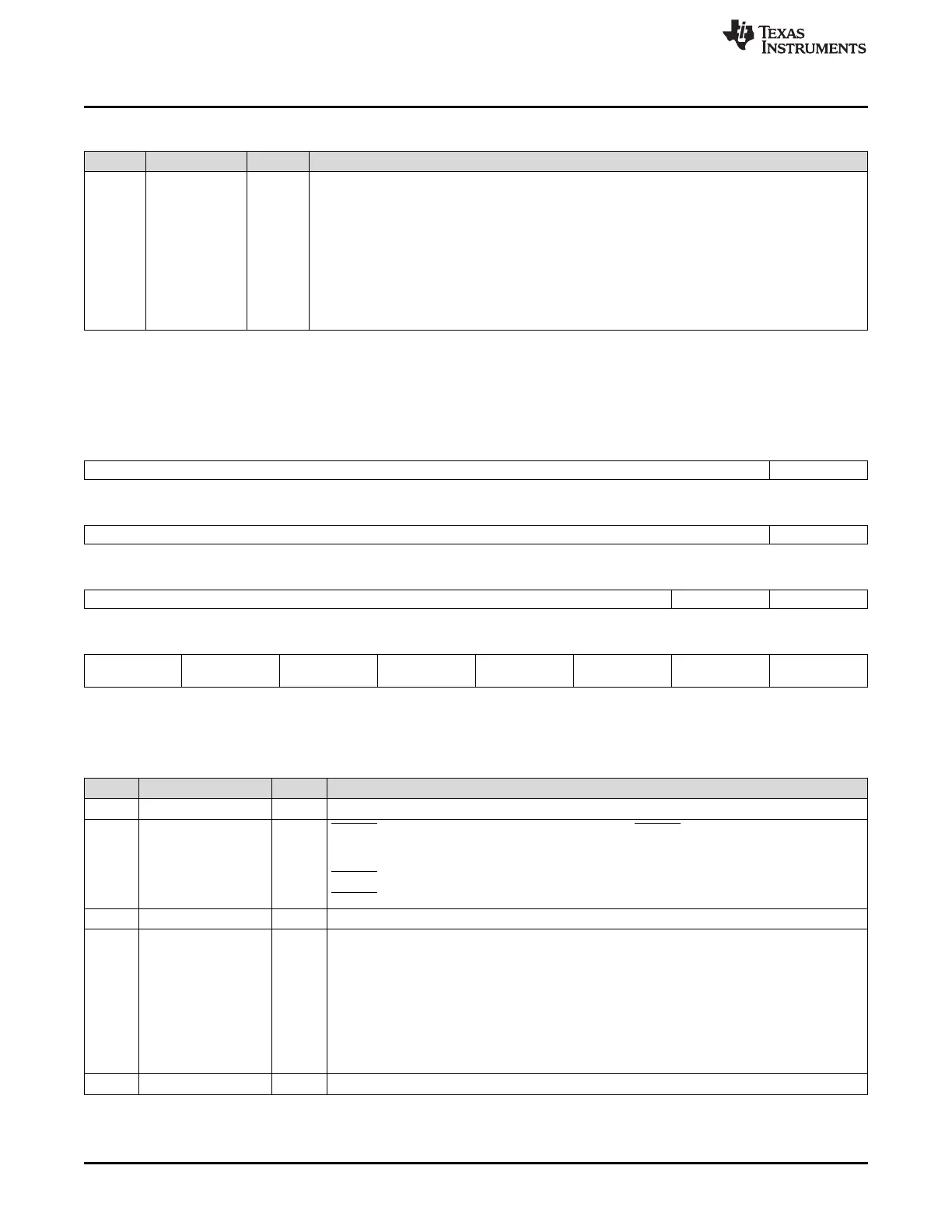
28.3.3 SPI Interrupt Register (SPIINT0)
Figure 28-34. SPI Interrupt Register (SPIINT0) [offset = 08h]
31 25 24
Reserved ENABLEHIGHZ
R-0 R/W-0
23 17 16
Reserved DMAREQEN
R-0 R/W-0
15 10 9 8
Reserved TXINTENA RXINTENA
R-0 R/W-0 R/W-0
7 6 5 4 3 2 1 0
Reserved RXOVRNINT
ENA
Reserved BITERR
ENA
DESYNC
ENA
PARERR
ENA
TIMEOUT
ENA
DLENERR
ENA
R-0 R/W-0 R-0 R/W-0 R/W-0 R/W-0 R/W-0 R/W-0
LEGEND: R/W = Read/Write; R = Read only; -n = value after reset
Table 28-11. SPI Interrupt Register (SPIINT0) Field Descriptions
Bit Field Value Description
31-25 Reserved 0 Reads return 0. Writes have no effect.
24 ENABLEHIGHZ SPIENA pin high-impedance enable. When active, the SPIENA pin (when it is configured as a
WAIT functional output signal in a slave SPI) is forced to high-impedance when not driving a
low signal. If inactive, then the pin will output both a high and a low signal.
0 SPIENA pin is pulled high when not active.
1 SPIENA pin remains high-impedance when not active.
23-17 Reserved 0 Reads return 0. Writes have no effect.
16 DMAREQEN DMA request enable. Enables the DMA request signal to be generated for both receive and
transmit channels. Enable DMA REQ only after setting the SPIEN bit to 1.
0 DMA is not used.
1 DMA requests will be generated.
Note: A DMA request will be generated on the TX DMA REQ line each time a word is
copied to the shift register either from TXBUF or directly from SPIDAT0/SPIDAT1 writes.
Note: A DMA request will be generated on the RX DMA REQ line each time a word is
copied to the SPIBUF register either from RXBUF or directly from the shift register.
15-10 Reserved 0 Reads return 0. Writes have no effect.

 Loading...


