DCC Control Registers
www.ti.com
550
SPNU563A–March 2018
Submit Documentation Feedback
Copyright © 2018, Texas Instruments Incorporated
Dual-Clock Comparator (DCC) Module
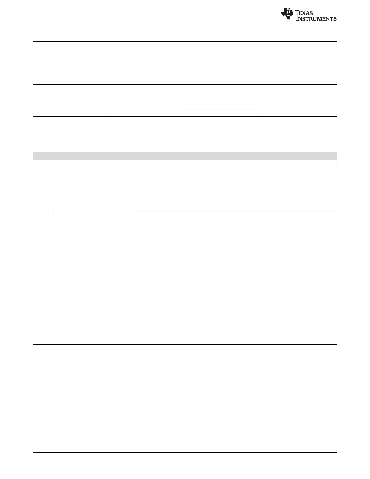
15.4.1 DCC Global Control Register (DCCGCTRL)
Figure 15-7 and Table 15-2 describe the DCC Global Control register.
Figure 15-7. DCC Global Control Register (DCCGCTRL) [offset = 00]
31 16
Reserved
R-0
15 12 11 8 7 4 3 0
DONE INT ENA SINGLE SHOT ERR ENA DCC ENA
R/WP-5h R/WP-5h R/WP-5h R/WP-5h
LEGEND: R/W = Read/Write; R = Read only; WP = Write in privileged mode only; -n = value after reset
Table 15-2. DCC Global Control Register (DCCGCTRL) Field Descriptions
Bit Field Value Description
31-16 Reserved 0 Reads return 0. Writes have no effect.
15-12 DONE INT ENA Done Interrupt Enable.
Any operation mode read, privileged mode write:
5h No interrupt is generated when the DONE flag is set in the DCC Status (DCCSTAT)
register.
Others DONE interrupt is generated when the DONE flag is set in the DCC Status (DCCSTAT)
register.
11-8 SINGLE SHOT Single-Shot Mode Enable.
Any operation mode read, privileged mode write:
Ah DCC stops counting when counter0 and valid0 both reach zero.
Bh DCC stops counting when counter1 reaches zero.
Others DCC counts continuously and only stops when an error occurs.
7-4 ERR ENA Error Interrupt Enable.
Any operation mode read, privileged mode write:
5h No interrupt is generated when the ERR flag is set in the DCC Status (DCCSTAT) register.
Others ERROR interrupt is generated when the ERR flag is set in the DCC Status (DCCSTAT)
register.
3-0 DCC ENA DCC Enable.
Any operation mode read, privileged mode write:
5h All DCC counters are stopped and error-checking is disabled. When an error occurs, the
counters stop and this field is set to 5h automatically disabling the DCC counter in
hardware.
Others Read: Counters are enabled.
Write: Load counters with their seed values and begin counting. It is recommended to write
Ah to enable counters to protect against single-bit errors.

 Loading...


