1 time quantum
(t
q
)
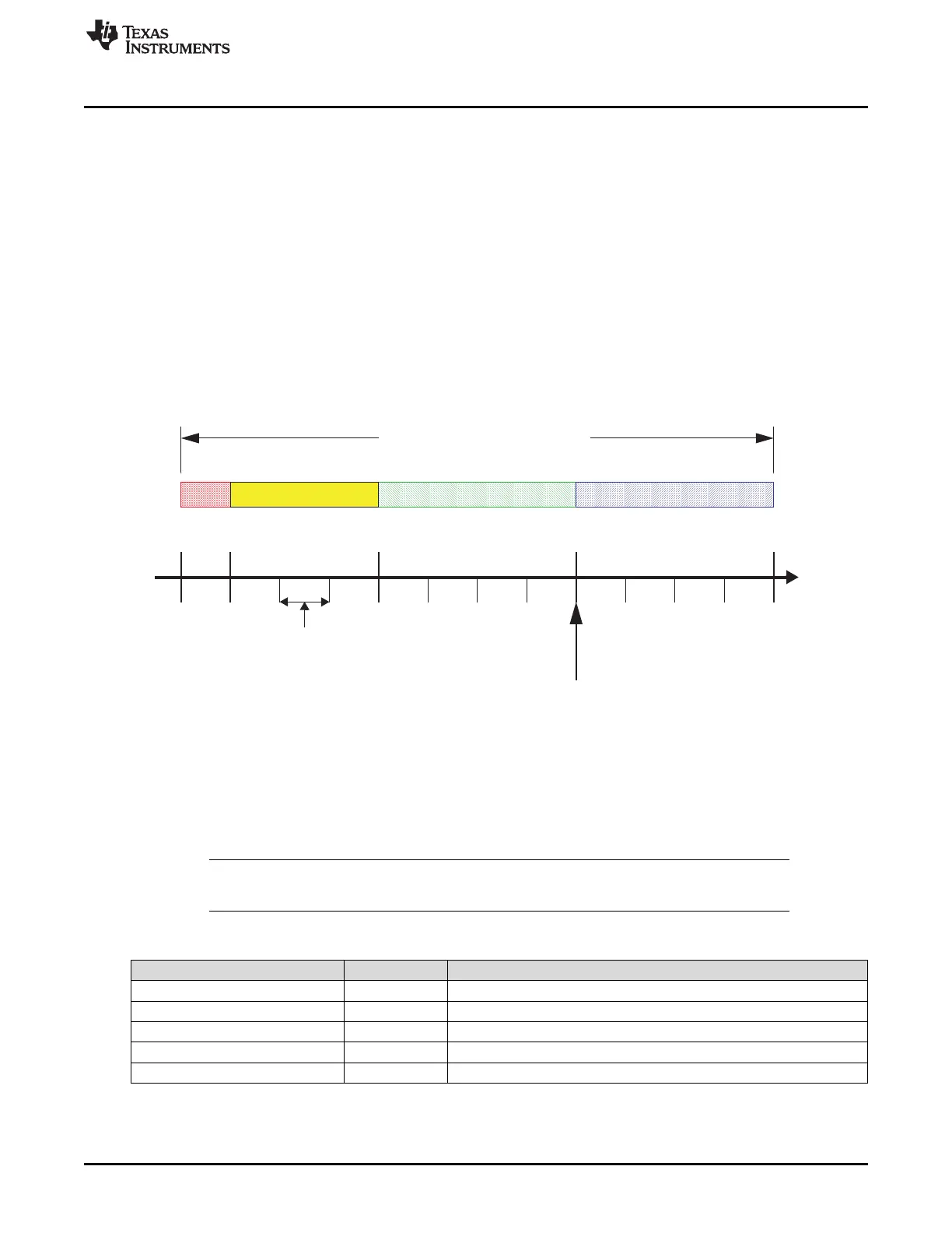
Sync_ Prop_Seg Phase_Seg1 Phase_Seg2
Sample point
Nominal CAN bit time
Seg
www.ti.com
CAN Bit Timing
1421
SPNU563A–March 2018
Submit Documentation Feedback
Copyright © 2018, Texas Instruments Incorporated
Controller Area Network (DCAN) Module
27.3 CAN Bit Timing
The DCAN supports bit rates between less than 1 kBit/s and 1000 kBit/s.
Each member of the CAN network has its own clock generator, typically derived from a crystal oscillator.
The Bit timing parameters can be configured individually for each CAN node, creating a common Bit rate
even though the CAN nodes’ oscillator periods (f
osc
) may be different.
27.3.1 Bit Time and Bit Rate
According to the CAN specification, the Bit time is divided into four segments (see Figure 27-2):
• Synchronization Segment (Sync_Seg)
• Propagation Time Segment (Prop_Seg)
• Phase Buffer Segment 1 (Phase_Seg1)
• Phase Buffer Segment 2 (Phase_Seg2)
Figure 27-2. Bit Timing
Each segment consists of a specific number of time quanta. The length of one time quantum, (t
q
), which is
the basic time unit of the bit time, is given by the CAN_CLK and the Baud Rate Prescalers (BRPE and
BRP). With these two Baud Rate Prescalers combined, divider values from 1 to 1024 can be programmed:
t
q
= Baud Rate Prescaler / CAN_CLK
Apart from the fixed length of the synchronization segment, these numbers are programmable.
Table 27-1 describes the minimum programmable ranges required by the CAN protocol. A given bit rate
may be met by different Bit time configurations.
NOTE: For proper functionality of the CAN network, the physical delay times and the oscillator’s
tolerance range have to be considered.
Table 27-1. Parameters of the CAN Bit Time
Parameter Range Remark
Sync_Seg 1 t
q
(fixed) Synchronization of bus input to CAN_CLK
Prop_Seg [1 … 8] t
q
Compensates for the physical delay times
Phase_Seg1 [1 … 8] t
q
May be lengthened temporarily by synchronization
Phase_Seg2 [1 … 8] t
q
May be shortened temporarily by synchronization
Synchronization Jump Width (SJW) [1 … 4] t
q
May not be longer than either Phase Buffer Segment

 Loading...


