MMR Registers
OCP MMR interface
Threshold
Compare Block
SCM Control
Block
active_ia_o(n-1:0)
active_ta_o(m-1:0)
Req2accept from each IA
Req2resp from each IA
err_event
Keys/Control
signals
To_clear
Dtc_soft_reset(3:0)
Global_error_clr
Hwchkr_sdc_soft_reset
CLKSTOPPEDm_0/1
ACPIDLE
Parity_diagnostic_enable
www.ti.com
Module Operation
255
SPNU563A–March 2018
Submit Documentation Feedback
Copyright © 2018, Texas Instruments Incorporated
SCR Control Module (SCM)
3.2 Module Operation
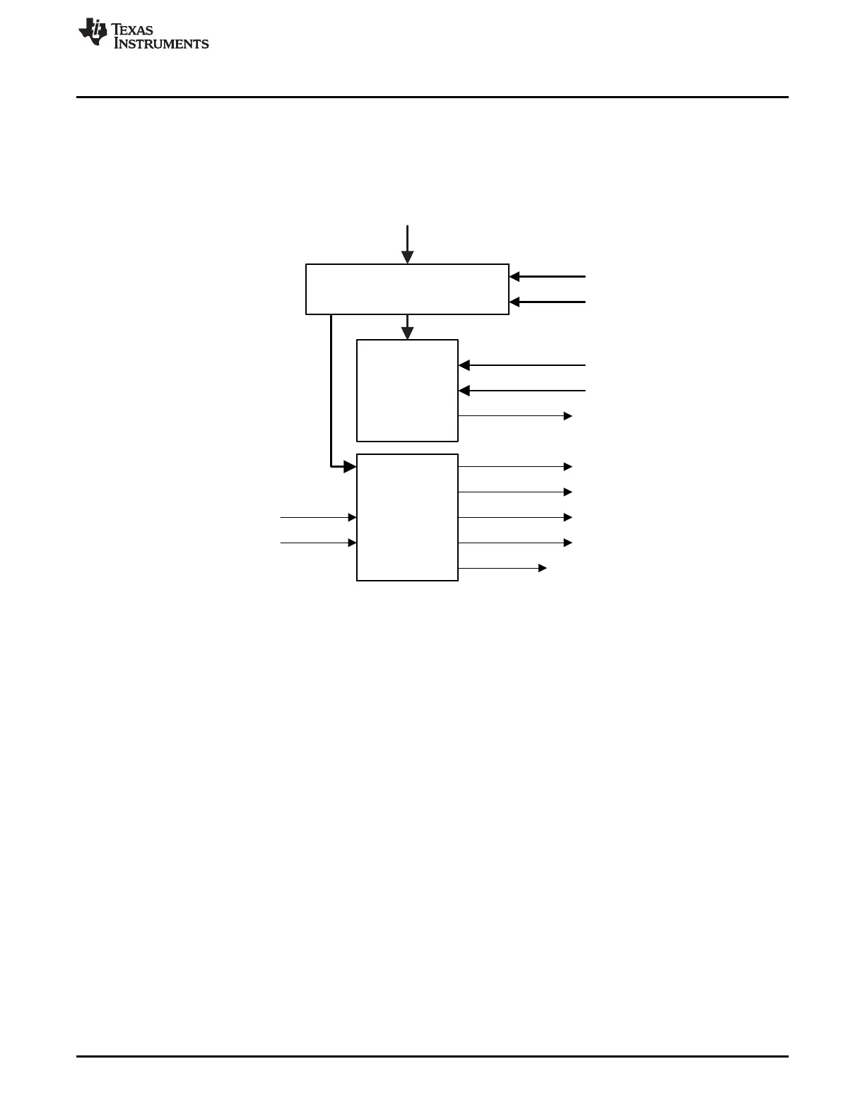
3.2.1 Block Diagram
Figure 3-2 shows the block diagram of SCM.
Figure 3-2. SCM Block Diagram
n is the maximum number of IA. m is the maximum number of TA.
3.2.2 Timeout Threshold Compare Block
The threshold compare block (Figure 3-3) takes the real-time counters (command request to command
accepted and command request to command response) from each IA of the interconnect hardware
checker module and compare against the corresponding threshold value in SCM every cycle. If any IA
comparison fails, the SCM module will update the corresponding status bit in SCMIAERR0STAT and
SCMIAERR1STAT registers. SCMIAERR0STAT logs the time out error for command request to command
accepted. SCMIAERR1STAT logs the time out error for command request to command response. Any
status bit set in these two status registers will trigger an error event to ESM (Error Signaling Module) and
will not trigger again until cleared by CPU.
Any of these status bits can be cleared by a privilege write to the individual bit. The write clear from CPU
to these status bits will always take higher priority than setting of the status bits from the interconnect.

 Loading...


