www.ti.com
RTI Control Registers
597
SPNU563A–March 2018
Submit Documentation Feedback
Copyright © 2018, Texas Instruments Incorporated
Real-Time Interrupt (RTI) Module
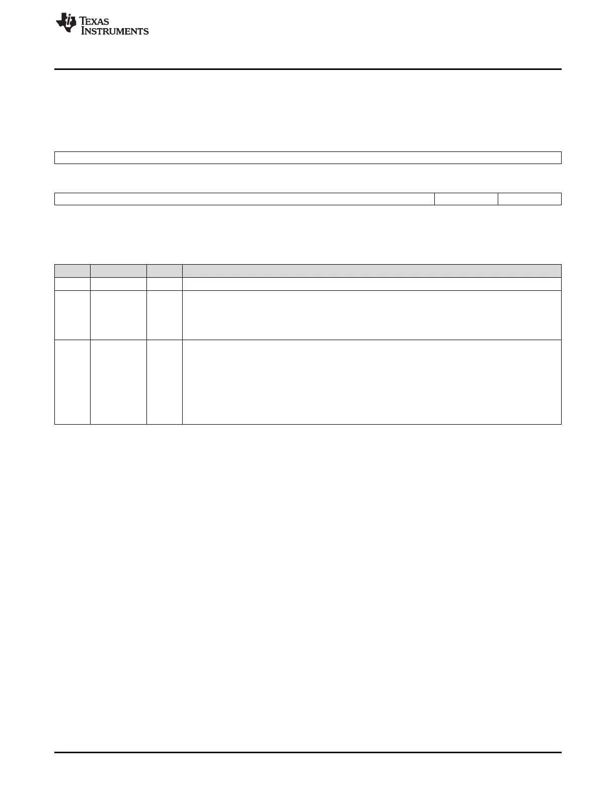
17.3.2 RTI Timebase Control Register (RTITBCTRL)
The timebase control register selects if the free running counter 0 is incremented by RTICLK or NTU. This
register is shown in Figure 17-13 and described in Table 17-3.
Figure 17-13. RTI Timebase Control Register (RTITBCTRL) [offset = 04h]
31 8
Reserved
R-0
7 2 1 0
Reserved INC TBEXT
R-0 R/WP-0 R/WP-0
LEGEND: R/W = Read/Write; R = Read only; WP = Write in privileged mode only; -n = value after reset
Table 17-3. RTI Timebase Control Register (RTITBCTRL) Field Descriptions
Bit Field Value Description
31-2 Reserved 0 Reads return 0. Writes have no effect.
1 INC Increment free running counter 0. This bit determines whether the free running counter 0 (RTIFRC0) is
automatically incremented if a failing clock on the NTU signal is detected.
0 RTIFRC0 will not be incremented on a failing external clock.
1 RTIFRC0 will be incremented on a failing external clock.
0 TBEXT Timebase external. This bit selects whether the free running counter 0 (RTIFRC0) is clocked by the
internal up counter 0 (RTIUC0) or from the external signal NTU. Setting the TBEXT bit from 0 to 1 will
not increment RTIFRC0, since RTIUC0 is reset.
When the timebase supervisor circuit detects a missing clock edge, then the TBEXT bit is reset.
Only the software can select whether the external signal should be used.
0 RTIUC0 clocks RTIFRC0.
1 NTU clocks RTIFRC0.

 Loading...


