RTI Control Registers
www.ti.com
598
SPNU563A–March 2018
Submit Documentation Feedback
Copyright © 2018, Texas Instruments Incorporated
Real-Time Interrupt (RTI) Module
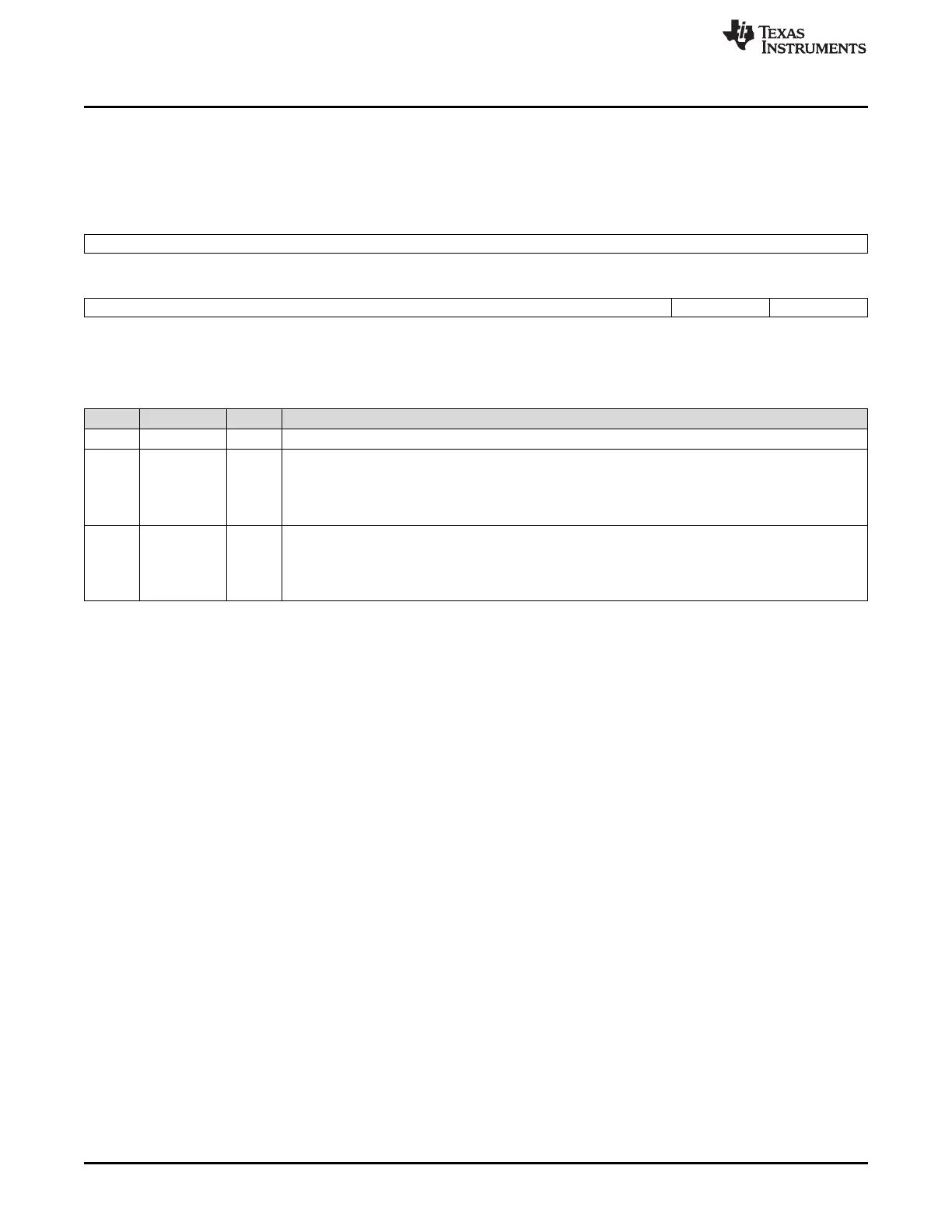
17.3.3 RTI Capture Control Register (RTICAPCTRL)
The capture control register controls the capture source for the counters. This register is shown in
Figure 17-14 and described in Table 17-4.
Figure 17-14. RTI Capture Control Register (RTICAPCTRL) [offset = 08h]
31 8
Reserved
R-0
7 2 1 0
Reserved CAPCNTR1 CAPCNTR0
R-0 R/WP-0 R/WP-0
LEGEND: R/W = Read/Write; R = Read only; WP = Write in privileged mode only; -n = value after reset
Table 17-4. RTI Capture Control Register (RTICAPCTRL) Field Descriptions
Bit Field Value Description
31-2 Reserved 0 Reads return 0. Writes have no effect.
1 CAPCNTR1 Capture counter 1. This bit determines which external interrupt source triggers a capture event of
RTIUC1 and RTIFRC1.
0 Capture of RTIUC1/ RTIFRC1 is triggered by capture event source 0.
1 Capture of RTIUC1/ RTIFRC1 is triggered by capture event source 1.
0 CAPCNTR0 Capture counter 0. This bit determines which external interrupt source triggers a capture event of
RTIUC0 and RTIFRC0.
0 Capture of RTIUC0/ RTIFRC0 is triggered by capture event source 0.
1 Capture of RTIUC0/ RTIFRC0 is triggered by capture event source 1.

 Loading...


