www.ti.com
Instruction Set
1129
SPNU563A–March 2018
Submit Documentation Feedback
Copyright © 2018, Texas Instruments Incorporated
High-End Timer (N2HET) Module
23.6.3.24 WCAPE (Software Capture Word and Event Count)
Syntax WCAPE {
[brk={OFF | ON}]
[next={label | 9-bit unsigned integer}]
[reqnum={3-bit unsigned integer}
[request={NOREQ | GENREQ | QUIET}]
[control={OFF | ON}]
[prv={OFF | ON}]
[cond_addr={label | 9-bit unsigned integer}
pin ={pin number}
event={NOCOND | FALL | RISE | BOTH}
[reg={A | B | R | S | T | NONE}]
[irq={OFF | ON}]
[ts_data={25-bit unsigned integer]
[ec_data={7-bit unsigned integer}]
}
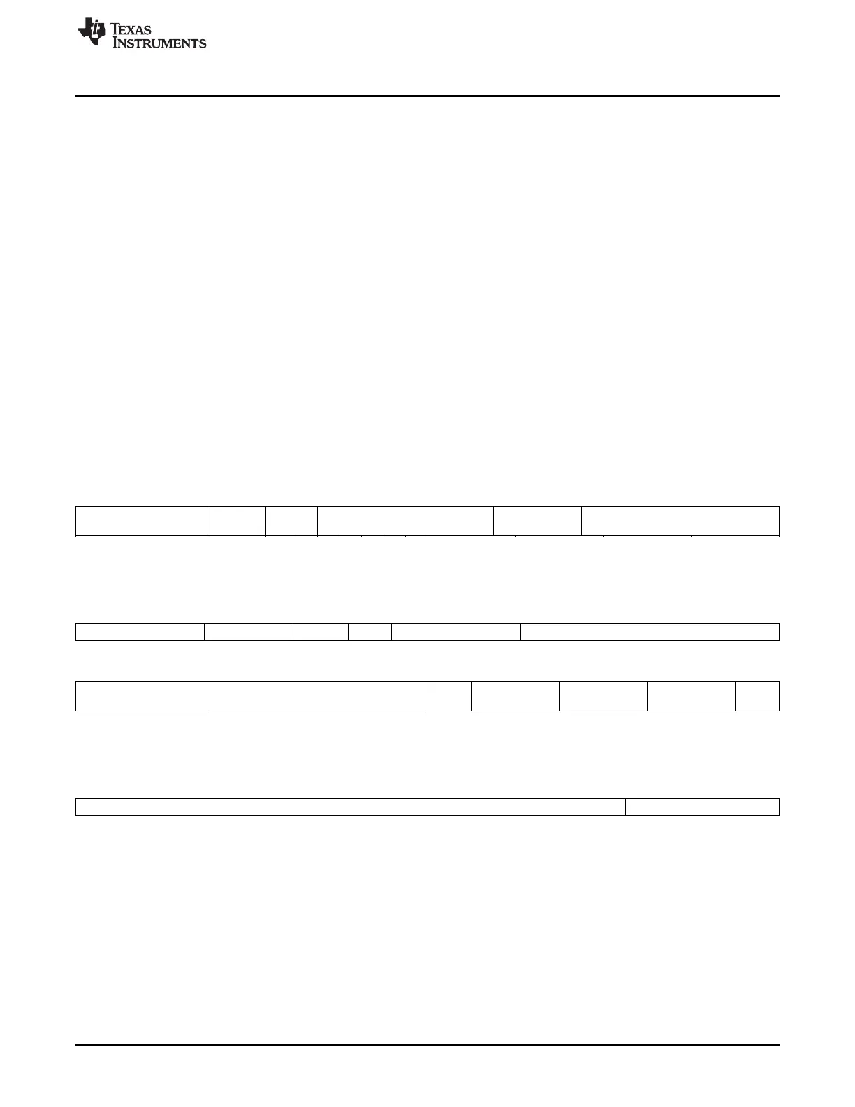
Figure 23-189. WCAPE Program Field (P31:P0)
31 26 25 23 22 21 13 12 9 8 0
0 Request
Number
BRK Next program address 1000 Reserved
6 3 1 9 4 9
Figure 23-190. WCAPE Control Field (C31:C0)
31 29 28 27 26 25 24 23 22 21 16
Reserved Request type Control Prv. Reserved Conditional address
3 2 1 1 3 9
15 13 12 8 7 6 5 4 3 2 1 0
Conditional address Pin select Ext
Reg
Capture
condition
Reserved Register select Int.
ena
9 5 1 2 2 2 1
Figure 23-191. WCAPE Data Field (D31:D0)
31 7 6 0
Time Stamp Edge Counter
25 7
Cycles One
Register modified None
Description This instruction captures the selected register into the data field [D31:D7] and
increments an event counter [D6:D0] if the specified capture condition is true
on the selected pin. This instruction can be used with all pins, but the time
stamp [D31:D7] has loop resolution only.

 Loading...


