Clocks
www.ti.com
150
SPNU563A–March 2018
Submit Documentation Feedback
Copyright © 2018, Texas Instruments Incorporated
Architecture
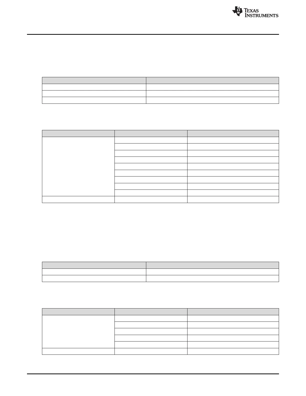
2.4.6.4.1 DCC1
As can be seen, the main oscillator (OSCIN) can be used for counter 0 as a “known-good” reference
clock. The clock for counter 1 can be selected from among 8 options. Refer to the DCC module chapter
for more details on the DCC usage.
Table 2-14. DCC1 Counter 0 Clock Inputs
Clock Source [3–0] Clock / Signal Name
All other values oscillator (OSCIN)
5h HF LPO
Ah test clock (TCK)
Table 2-15. DCC1 Counter 1 Clock / Signal Inputs
Key [3–0] Clock Source [3–0] Clock / Signal Name
Ah
0h PLL1 free-running clock output
1h PLL2 free-running clock output
2h LF LPO
3h HF LPO
4h Flash pump oscillator
5h EXTCLKIN1
6h EXTCLKIN2
7 Reserved
8h-Fh VCLK
All other values any value N2HET1[31]
2.4.6.4.2 DCC2
As can be seen, the main oscillator (OSCIN) can be used for counter 0 as a “known-good” reference
clock. The clock for counter 1 can be selected from among 2 options. Refer to the DCC module chapter
for more details on the DCC usage.
Table 2-16. DCC2 Counter 0 Clock Inputs
Clock Source [3–0] Clock / Signal Name
others oscillator (OSCIN)
0xA test clock (TCK)
Table 2-17. DCC2 Counter 1 Clock / Signal Inputs
Key [3–0] Clock Source [3–0] Clock / Signal Name
Ah
0h Reserved
1h PLL2 post_ODCLK/8
2h PLL2 post_ODCLK/16
3h-7h Reserved
8h-Fh VCLK
All other values any value N2HET2[0]
 Loading...


