www.ti.com
Control Registers
1561
SPNU563A–March 2018
Submit Documentation Feedback
Copyright © 2018, Texas Instruments Incorporated
Multi-Buffered Serial Peripheral Interface Module (MibSPI) with Parallel Pin
Option (MibSPIP)
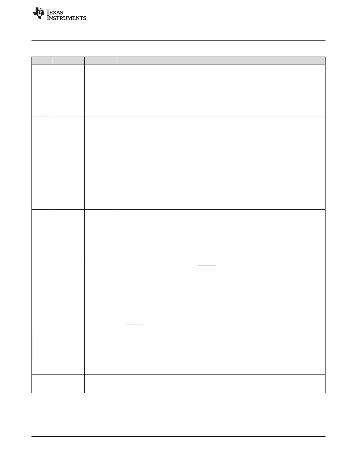
Table 28-26. SPI Receive Buffer Register (SPIBUF) Field Descriptions (continued)
Bit Field Value Description
28 BITERR Bit error. There was a mismatch of internal transmit data and transmitted data.
Note: This flag is cleared to 0 when the RXDATA field of the SPIBUF register is read.
0 No bit error occurred.
1 A bit error occurred. The SPI samples the signal of the transmit pins (master: SIMOx, slave:
SOMIx) at the receive point (one-half clock cycle after the transmit point). If the sampled value
differs from the transmitted value, a bit error is detected and the BITERR flag is set. Possible
reasons for a bit error include noise, an excessively high bit rate, capacitive load, or another
master/slave trying to transmit at the same time.
27 DESYNC Desynchronization of slave device. This bit is valid in master mode only.
The master monitors the ENA signal coming from the slave device and sets the DESYNC flag if
ENA is deactivated before the last reception point or after the last bit is transmitted plus t
T2EDELAY
.
If DESYNCENA is set, an interrupt is asserted. Desynchronization can occur if a slave device
misses a clock edge coming from the master.
Note: In the Compatibility Mode MibSPI, under some circumstances it is possible for a
desync error detected for the previous buffer to be visible in the current buffer. This is
because the receive completion flag/interrupt is generated when the buffer transfer is
completed. But desynchronization is detected after the buffer transfer is completed. So, if
the VBUS master reads the received data quickly when an RXINT is detected, then the
status flag may not reflect the correct desync condition. In multi-buffer mode, the desync
flag is always guaranteed to be for the current buffer.
Note: This flag is cleared to 0 when the RXDATA field of the SPIBUF register is read.
0 No slave desynchronization is detected.
1 A slave device is desynchronized.
26 PARITYERR Parity error. The calculated parity differs from the received parity bit.
If the parity generator is enabled (selected individually for each buffer) an even or odd parity bit is
added at the end of a data word. During reception of the data word, the parity generator calculates
the reference parity and compares it to the received parity bit. If a mismatch is detected, the
PARITYERR flag is set.
Note: This flag is cleared to 0 when the RXDATA field of the SPIBUF register is read.
0 No parity error is detected.
1 A parity error occurred.
25 TIMEOUT Time-out because of non-activation of SPIENA pin.
The SPI generates a time-out when the slave does not respond in time by activating the ENA
signal after the chip select signal has been activated. If a time-out condition is detected, the
corresponding chip select is deactivated immediately and the TIMEOUT flag is set. In addition, the
TIMEOUT flag in the status field of the corresponding buffer and in the SPI Flag Register
(SPIFLG) is set.
This bit is valid only in master mode.
Note: This flag is cleared to 0 when the RXDATA field of the SPIBUF register is read.
0 No SPIENA pin time-out occurred.
1 An SPIENA signal time-out occurred.
24 DLENERR Data length error flag.
Note: This flag is cleared to 0 when the RXDATA field of the SPIBUF register is read.
0 No data-length error occurred.
1 A data length error occurred.
23-16 LCSNR 0-FFh Last chip select number. LCSNR in the status field is a copy of CSNR in the corresponding control
field. It contains the chip select number that was activated during the last word transfer.
15-0 RXDATA 0-FFFFh SPI receive data. This is the received word, transferred from the receive shift-register at the end of
a transfer. Regardless of the programmed character length and the direction of shifting, the
received data is stored right-justified in the register.

 Loading...


