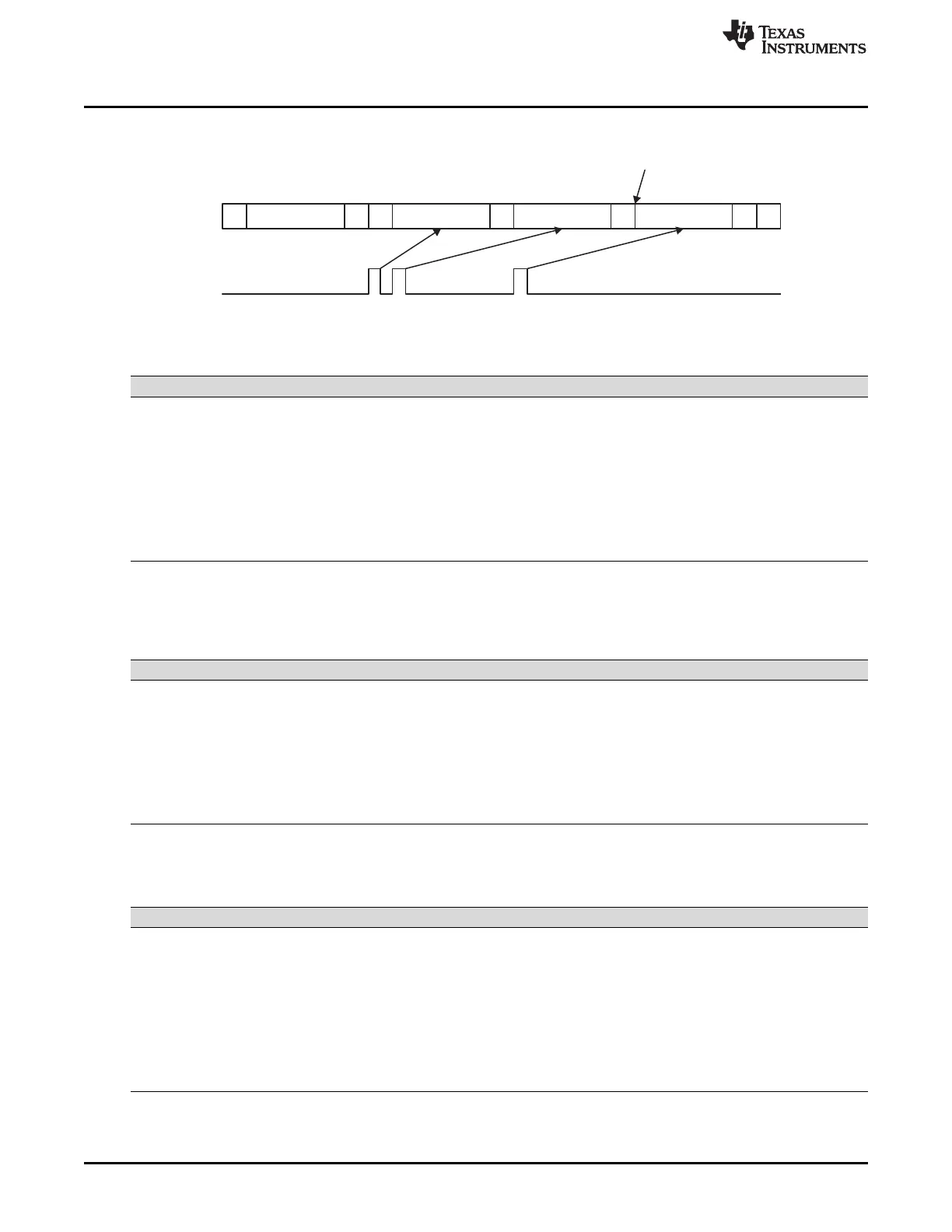
Master-transmitter (repeat mode)
(Please note that this behavior is independent of BCM bit)
S A A A nA PWSlave address
Data Data Data
Interrupt
Set STP bit
I2C Control Registers
www.ti.com
1792
SPNU563A–March 2018
Submit Documentation Feedback
Copyright © 2018, Texas Instruments Incorporated
Inter-Integrated Circuit (I2C) Module
Figure 31-23. Typical Timing Diagram of Repeat Mode
(1)
P = Stop condition; S = Start condition; A = Acknowledge bit; D = data
Table 31-16. I2C Module Condition, Bus Activity, and Mode
RM STT STP Condition Bus Activities
(1)
Mode
0 0 0 Idle None N/A
0 0 1 Stop P N/A
0 1 0 (Repeat) Start S-A-D..(n)..D Repeat n
0 1 1 (Repeat) Start-Stop S-A-D..(n)..D-P Repeat n
1 0 0 Idle None N/A
1 0 1 Stop P N/A
1 1 0 (Repeat) Start S-A-D-D-D-.... Continuous
1 1 1 Reserved None N/A
Table 31-17. I2C Module Operating Modes
FDF MST TRX Operating Mode
0 0 x Slave in non-FDF mode
0 1 0 Master receive in non-FDF mode
0 1 1 Master transmit in non-FDF mode
1 0 0 Slave receive in FDF mode
1 0 1 Slave transmit in FDF mode
1 1 0 Master receive in FDF mode
1 1 1 Master transmit in FDF mode
Table 31-18. Number of Bits Sent on Bus
BC2 BC1 BC0 Bits in FDF Bits with ACK
0 0 0 8 9
0 0 1 NA (reserved) NA (reserved)
0 1 0 2 3
0 1 1 3 4
1 0 0 4 5
1 0 1 5 6
1 1 0 6 7
1 1 1 7 8

 Loading...


