TC1796
Peripheral Units (Vol. 2 of 2)
Synchronous Serial Interface (SSC)
User’s Manual 20-39 V2.0, 2007-07
SSC, V2.1
Note: The SSOTC register timing parameters are latched by each TB register write
operation and remain latched during a consecutive serial transmission.
The Baud Rate Timer Reload Register BR contains the 16-bit reload value for the baud
rate timer.
INACT [5:4] rw Slave Output Select Inactive Delay
This bit field determines the number of inactive delay
clock cycles. A inactive delay clock cycle is always a
multiple of an SCLK shift clock period.
00
B
Zero inactive delay clock cycle selected
1)
01
B
One inactive delay clock cycle selected
10
B
Two inactive delay clock cycles selected
11
B
Three inactive delay clock cycles selected
SLSO7MOD 8rwSLSO7 Delayed Mode Selection
This bit selects the delayed mode for the SLSO7
slave select output.
0
B
Normal mode selected for SLSO7
1
B
Delayed mode selected for SLSO7
0 [7:6],
[31:9]
r Reserved
Read as 0; should be written with 0.
1) For getting a best case timing with no timing delays (see Figure 20-11), this bit field value should be set when
the SLSOn outputs are disabled (SSOC.OENn bits set to 0).
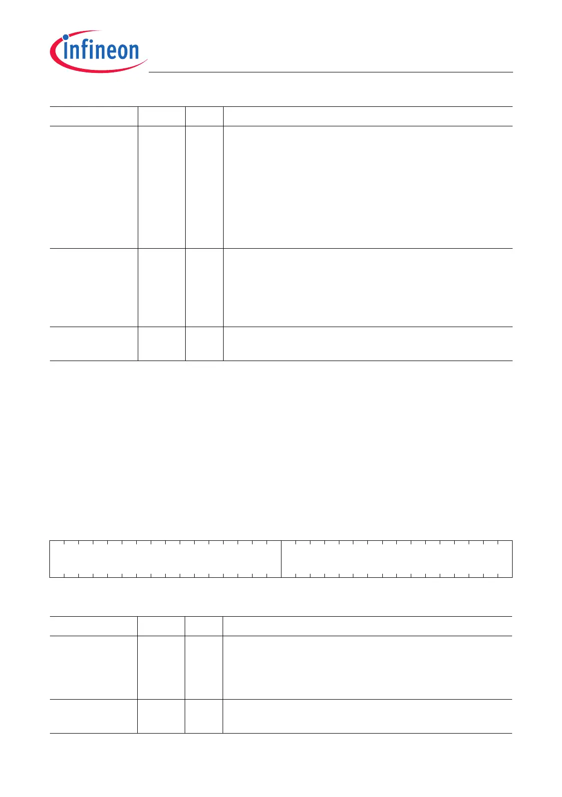
BR
Baud Rate Timer Reload Register (14
H
) Reset Value: 0000 0000
H
31 16 15 0
0BR_VALUE
rrw
Field Bits Type Description
BR_VALUE [15:0] rw Baud Rate Timer/Reload Register Value
Reading BR returns the 16-bit content of the baud
rate timer. Writing BR loads the baud rate timer reload
register with BR_VALUE.
0 [31:16] r Reserved
Read as 0; should be written with 0.
Field Bits Type Description

 Loading...