TC1796
Peripheral Units (Vol. 2 of 2)
Micro Second Channel (MSC)
User’s Manual 21-49 V2.0, 2007-07
MSC, V2.0
The Interrupt Control Register ICR holds the interrupt enable bits and interrupt pointers
of all four MSC interrupts.
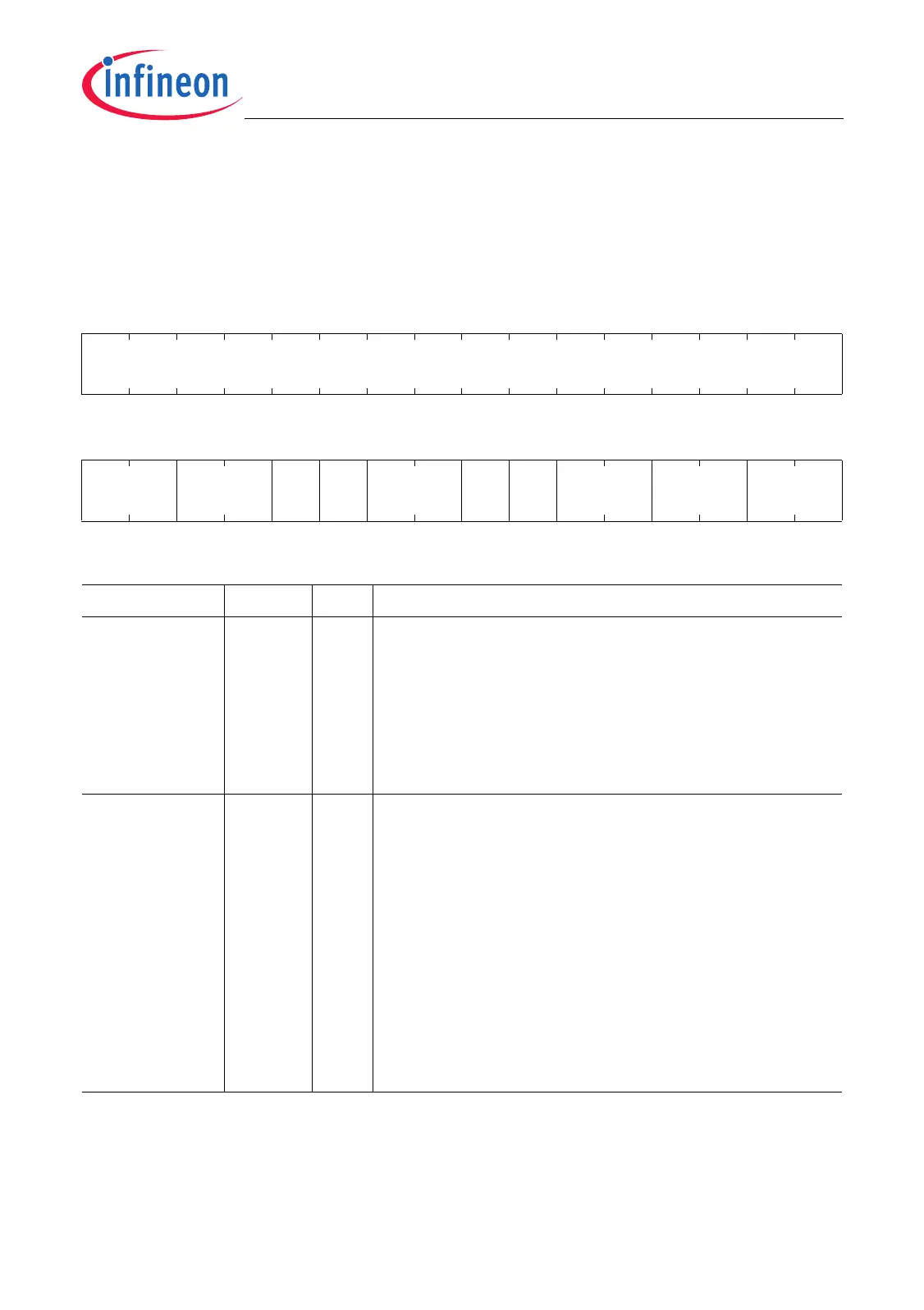
ICR
Interrupt Control Register (40
H
) Reset Value: 0000 0000
H
31 30 29 28 27 26 25 24 23 22 21 20 19 18 17 16
0
r
1514131211109876543210
RDIE RDIP TFIE 0 TFIP ECIE 0 ECIP EDIE EDIP
rw rw rw r rw rw r rw rw rw
Field Bits Type Description
EDIP [1:0] rw Data Frame Interrupt Node Pointer
EDIP selects the service request output line SRn
(n = 3-0) for the data frame interrupt.
00
B
Service request output SR0 selected
01
B
Service request output SR1 selected
10
B
Service request output SR2 selected
11
B
Service request output SR3 selected
EDIE [3:2] rw Data Frame Interrupt Enable
This bit field determines the enable conditions for the
data frame interrupt.
00
B
Interrupt generation disabled
01
B
An interrupt is generated when the last data bit
has been shifted out.
10
B
An interrupt is generated when the first data bit
has been shifted out, but only if DSC.NDBL is
not equal 00000
B
. This means, at least one
SRL bit must be shifted out for the first data bit
shifted interrupt to become active.
11
B
Interrupt generation disabled

 Loading...