TC1796
System Units (Vol. 1 of 2)
Clock System and Control
User’s Manual 3-17 V2.0, 2007-07
Clock, V2.0
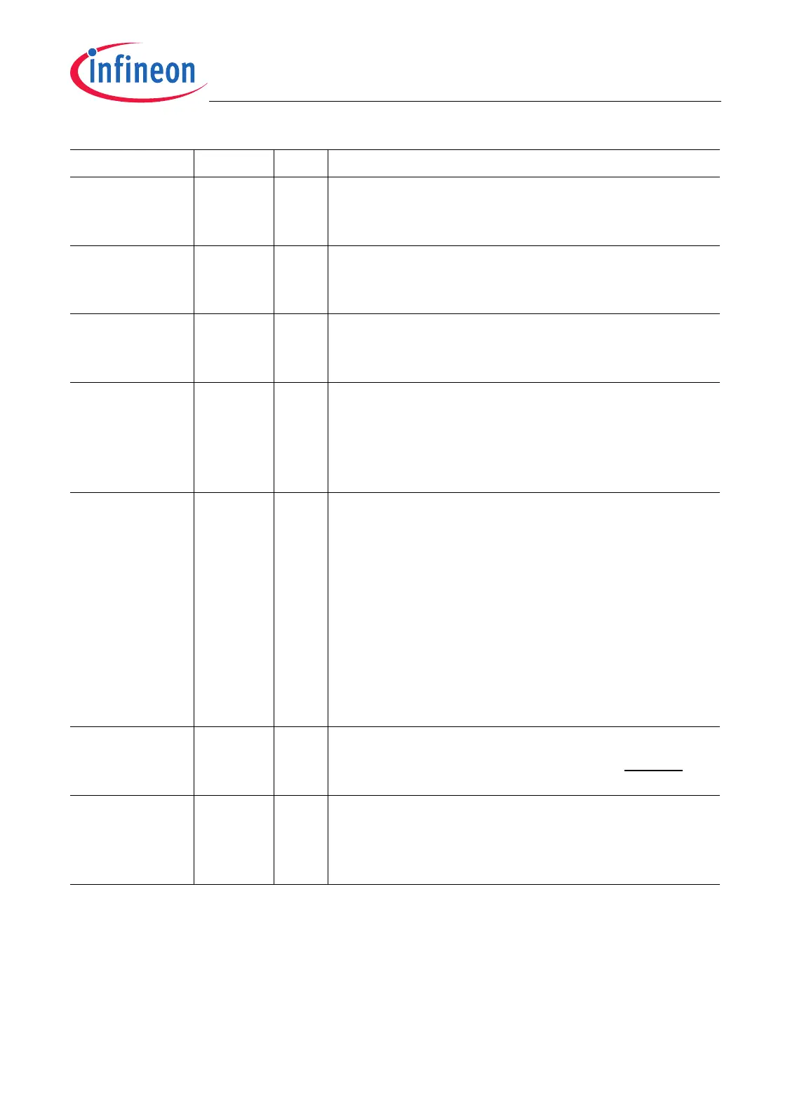
VCOSEL [7:6] rw VCO Range Selection
This bit field selects operating range of the VCO.
The coding is defined in Table 3-5.
KDIV [11:8] rw PLL K-Divider Selection
This bit field selects the K-Divider value. The coding
is defined in Table 3-4.
PDIV [15:13] rw PLL P-Divider Selection
This bit field selects the P-Divider value. The coding
is defined in Table 3-2.
NDIV [22:16] rw PLL N-Divider
This bit field selects the N-Divider value. The coding
is defined in Table 3-3.Note that only NDIV values
between 19
D
and 99
D
(means N-Divider values of
20
D
and 100
D
) are allowed.
OSCDISC 24 rwh Oscillator Disconnect
This bit is used to disconnect the divided f
OSC
clock
from the PLL in order to avoid unstable operation
due to noise or sporadic clock pulses coming from
the oscillator circuit while the PLL is still trying to
lock to invalid clock pulses.
0
B
Oscillator clock f
OSC
is connected to the PLL.
1
B
Oscillator clock f
OSC
is disconnected from the
PLL (default after reset)
This bit is set by hardware if a PLL loss-of-lock
failure is detected.
BYPPIN 29 rh Bypass Pin Status Flag
This bit indicates the state of the BYPASS input pin
as sampled with the last rising edge of PORST.
0 3, 4,12,
23,
[28:25],
[31:30]
r Reserved
Read as 0; should be written with 0.
Field Bits Type Description

 Loading...