TC1796
Peripheral Units (Vol. 2 of 2)
General Purpose Timer Array (GPTA)
User’s Manual 24-21 V2.0, 2007-07
GPTA, V2.0
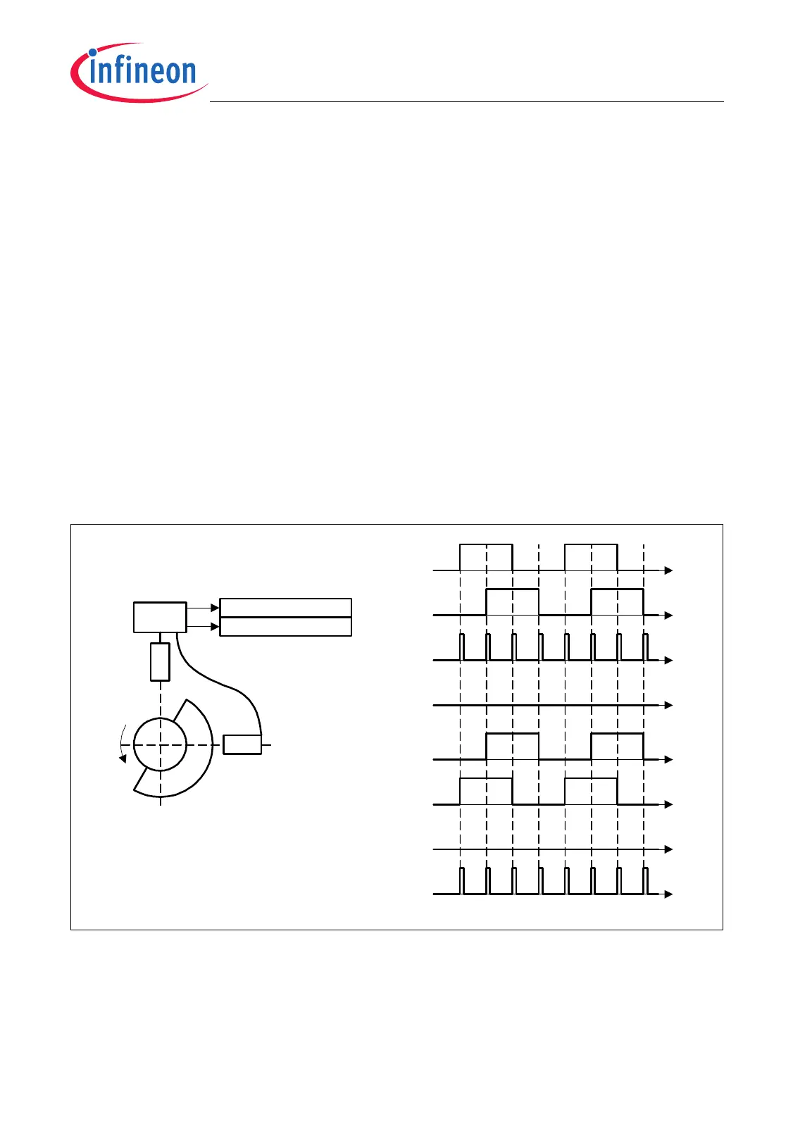
Positioning System With Two Sensors
The 2-sensor Mode is enabled when bit PDLCTR.TSEx is cleared. The sensors are
mounted at a 90° angle to each other (see Figure 24-13). The third sensor input of the
PDL module is internally disabled and DCM1/DCM3 cell inputs are driven by fed-through
FRC2/FPC5 output lines.
This configuration can measure an absolute position with a resolution of 90°. No error
conditions can be detected.
Figure 24-13 Interface Signals of a PDL in a 2-Sensor Positioning System
Figure 24-14 illustrates how the output signals of a 2-sensor system superimposed with
noise are processed by the PDL unit. Jitter pulses are completely compensated if they
do not occur on both signal lines simultaneously.
! Means not
Re Means rising edge
Fe Means falling edge
Forward ReS1*!S2 + S1*ReS2 + FeS1*S2 + !S1*FeS2
Backward ReS1*S2 + !S1*ReS2 + FeS1*!S2 + S1*FeS2
Position Forward_Counter - Backward_Counter
MCT05922
S1
S2
Forward
Backward
S2
Forward_Counter
Backward_Counter
Forward
S1
S2
Backward
S1

 Loading...