TC1796
Peripheral Units (Vol. 2 of 2)
General Purpose Timer Array (GPTA)
User’s Manual 24-57 V2.0, 2007-07
GPTA, V2.0
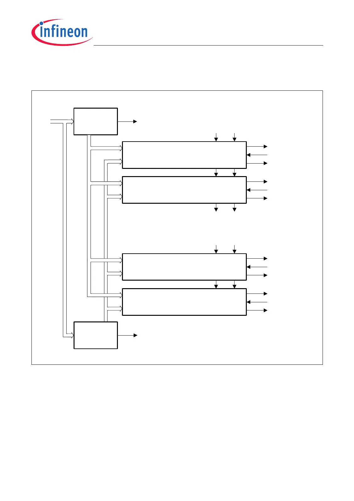
Figure 24-44 shows how the GTCs are arranged and connected to the adjacent GTCs
and with the Global Timers GT0 and GT1.
Figure 24-44 GTC Interconnections
Note: Cascading of GTCs is limited. TC1796 specific details are given on Page 24-272.
MCA05953
From GTC29
Global Timer Cell GTC00
M1I M0I
M1O M0O
GTC00IN
GTC00OUT
SQS00
GTV1 Bus / TGE1 / TEV1
GTV0 Bus / TGE0 / TEV0
Global Timer
GT0
Global Timer Cell GTC01
M1I M0I
M1O M0O
GTC01IN
GTC01OUT
SQS01
Global Timer Cell GTC30
M1I M0I
M1O M0O
GTC30IN
GTC30OUT
SQS30
Global Timer Cell GTC31
M1I M0I
GTC31IN
GTC31OUT
SQS31
To GTC02
Global Timer
GT1
SQT1
SQT0
Clock
Bus
.
.
.
.
.
.
.
.
.
.
.
.
.
.
.
.
00

 Loading...