TC1796
Peripheral Units (Vol. 2 of 2)
General Purpose Timer Array (GPTA)
User’s Manual 24-103 V2.0, 2007-07
GPTA, V2.0
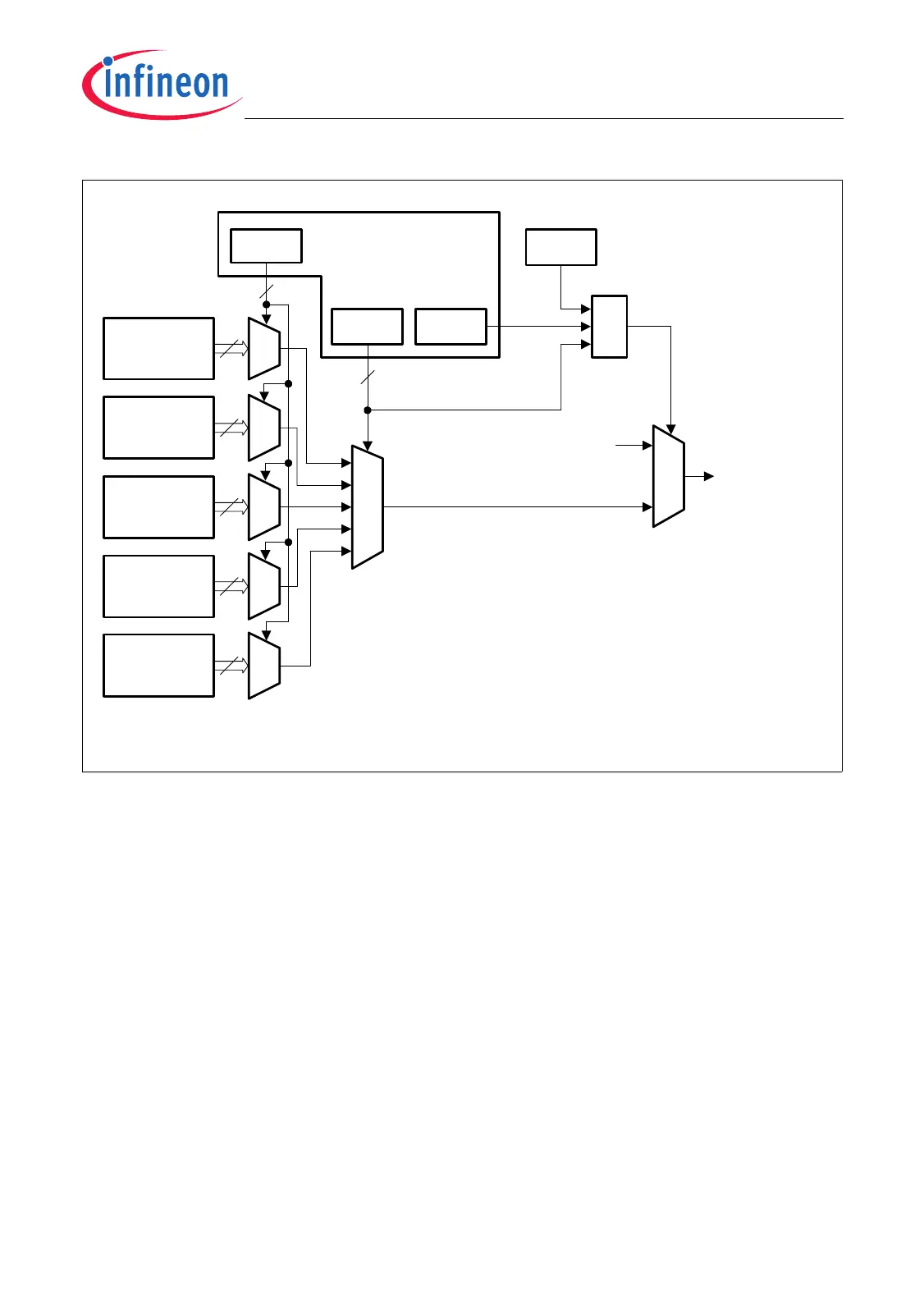
Figure 24-67 GTC Input Multiplexer Group (Programmer’s View)
The 1. level multiplexer is built up by five 8:1 multiplexers that are controlled in parallel
by bit field GIMLn. Bit field GIMGn controls the 2. level multiplexer and connects one of
the 1. level multiplexer outputs to one of the GIMGng outputs. The output of the 2. level
multiplexer is only connected to the input of an GTC if bit GIMENn (enable multiplexer
connection) is set, and bit MRACTL.AEN is set (multiplexer array enabled), and no
reserved bit combination of GIMGn is selected. If one of these conditions is not true, the
corresponding GIMG output will be held at a low level.
If one of these bit is not set, the corresponding GTC input will be held at a low level.
Two GTC Input Multiplexer Control Registers, GIMCRL and GIMCRH (see also
Page 24-198), are assigned to each of the GTC groups. Therefore, a total of eight
registers control the connections within the GTC input multiplexer of the GPTA module.
The GIMCRL registers control the GIMG output lines 0 to 3 and the GIMCRH registers
control the GIMG output lines 4 to 7. Table 24-11 lists all of the GTC Input Multiplexer
Control Registers with its control functions. Please note that all GTC Input Multiplexer
Registers
MCA05976
MUX
8
MUXMUX
010
001
000
2. Level
Mux
GIMLn
GIMGn
1. Level
Mux
GIMCRLg
GIMCRHg
(g = 0-4)
MUXMUX
MUX
011
100
To Input n of
GTC Group g
&
GIMENn
0
MUX
0
1
MAENn
MRACTL
Not a reserved
GIMGn bit combination
8
8
8
8
3
3
I/O Group
(GIMG0g)
I/O Group
(GIMG1g)
LTC Group
(GIMG2g)
LTC Group
(GIMG3g)
FPC/INT
Group
(GIMG4g)
 Loading...