TC1796
System Units (Vol. 1 of 2)
Clock System and Control
User’s Manual 3-38 V2.0, 2007-07
Clock, V2.0
Implementation
FDR registers are implemented for several modules of the TC1796. The name of these
FDR registers is always preceded by the module name (e.g. SSC0_FDR is the FDR
register for the SSC0 module). Table 3-9 defines which module is equipped with a FDR
register.
In the implementation parts of the modules using a fractional divider (see Table 3-9), the
signal f
OUT
is described as a clock signal and not as clock enable signal.
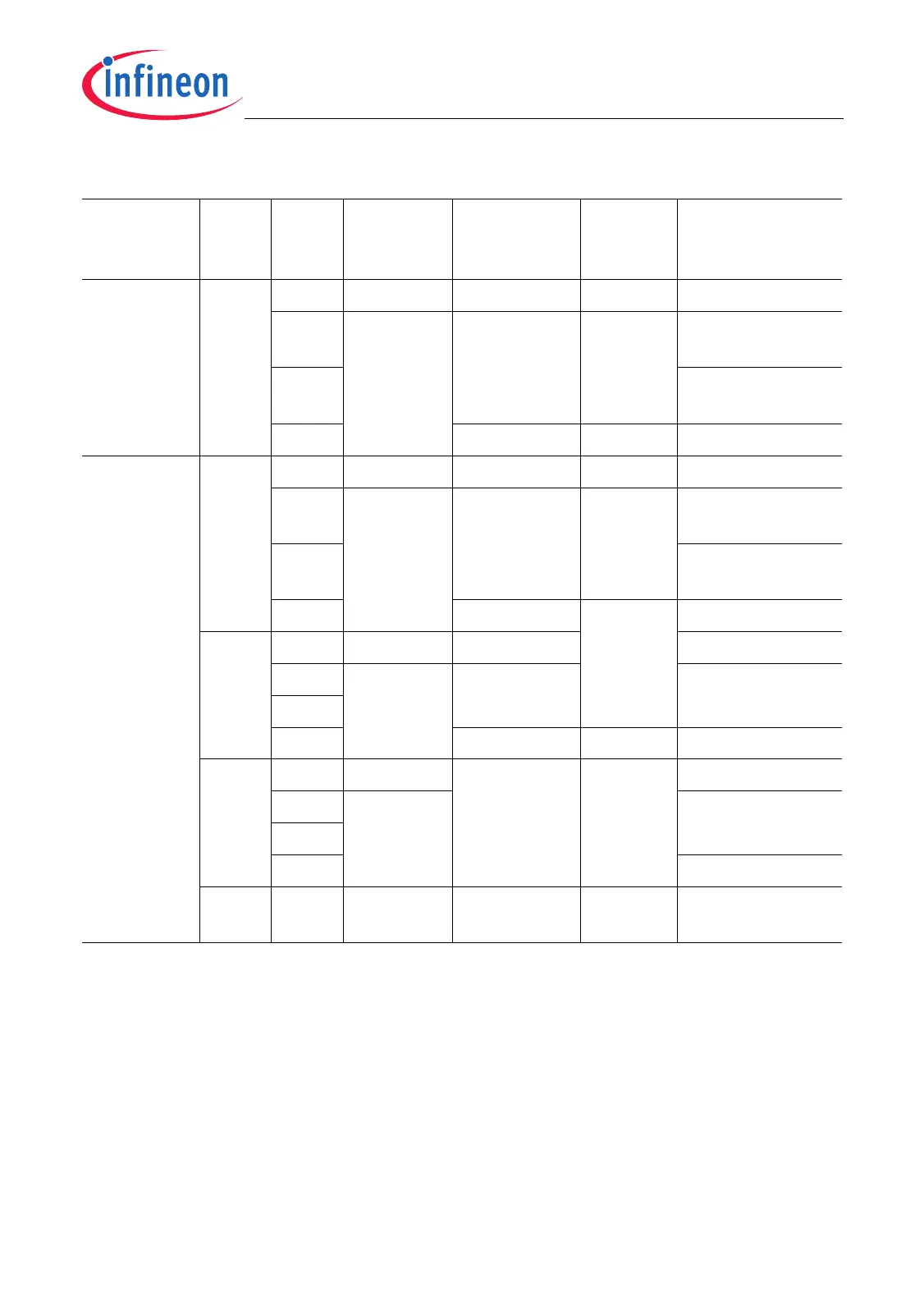
Table 3-8 Fractional Divider Function Table
Mode SC DM Reset Ext.
Divider
Signal
Result f
OUT
Operation of
Fractional
Divider
Normal
Mode
–00
B
1 unchanged inactive switched off
01
B
0 continuously
updated
1)
active normal divider
mode
10
B
fractional divider
mode
11
B
unchanged inactive switched off
Suspend
Mode
00
B
00
B
1 unchanged inactive switched off
01
B
0 continuously
updated
1)
active normal divider
mode
10
B
fractional divider
mode
11
B
unchanged inactive switched off
01
B
00
B
1 unchanged switched off
01
B
0 loaded with
3FF
H
halted
10
B
11
B
unchanged inactive switched off
10
B
00
B
1 loaded with
3FF
H
inactive switched off
01
B
0 halted
10
B
11
B
switched off
11
B
– 1 loaded with
3FF
H
inactive switched off
1) Each write operation to FDR with DM = 01
B
or 10
B
sets RESULT to 3FF
H
.

 Loading...