TC1796
Peripheral Units (Vol. 2 of 2)
Analog-to-Digital Converter (ADC)
User’s Manual 25-116 V2.0, 2007-07
ADC, V2.0
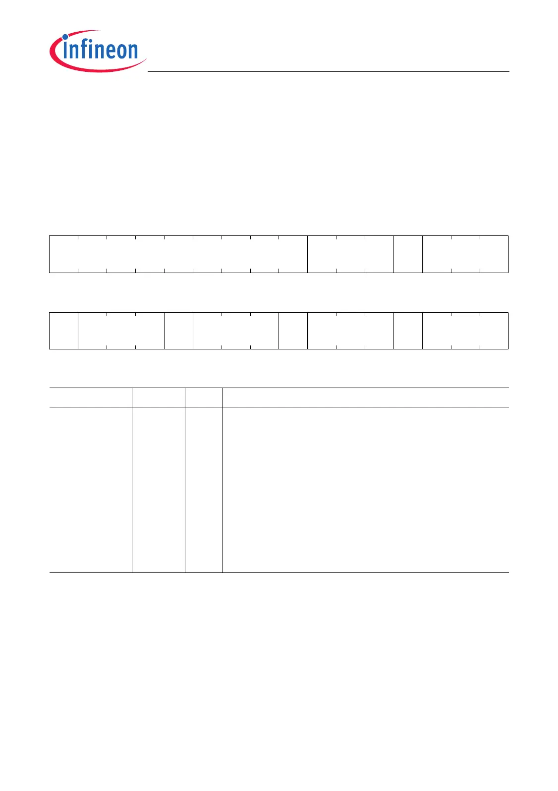
Trigger Gating Register
The registers TGADC0 and TGADC1 contain bit fields that determine which output
signals of the external request unit and the GPTA are used as trigger and gating inputs
of ADC0 and ADC1.
TGADCx (x = 0-1)
Trigger Gating ADCx Register (9C
H
+04
H
) Reset Value: 0000 0000
H
31 30 29 28 27 26 25 24 23 22 21 20 19 18 17 16
0 SW0GTSEL 0 EGTSEL
rrwrrw
1514131211109876543210
0 TTRSEL 0 QTRSEL 0 SW0TRSEL 0 ETRSEL
rrwrrwrrwrrw
Field Bits Type Description
ETRSEL [2:0] rw External Trigger Request Selection
This bit determines which trigger source will be used
for the ADCx external trigger request input ETR.
000
B
ETR = 0; no trigger function of ETR.
001
B
ETR is connected to GPTA0_OUT3.
010
B
ETR is connected to GPTA0_OUT11.
011
B
ETR is connected to GPTA0_OUT28.
100
B
ETR is connected to TOUT0.
101
B
ETR is connected to TOUT1.
110
B
ETR is connected to TOUT2.
111
B
ETR is connected to TOUT3.
 Loading...