TC1796
System Units (Vol. 1 of 2)
On-Chip Debug Support
User’s Manual 17-2 V2.0, 2007-07
OCDS, V2.0
TC1796. For detailed information about the TC1796ED functionality (e.g. required by
high-end emulation manufacturers), please contact local Infineon representatives.
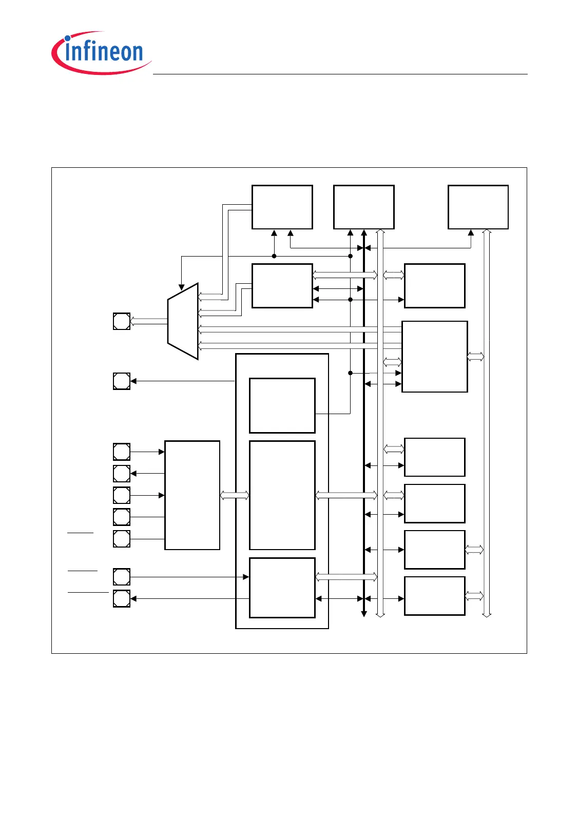
Figure 17-1 is a block diagram of the TC1796 OCDS based system.
Figure 17-1 OCDS Based System Block Diagram
Components
The OCDS of the TC1796 consists of the following building blocks:
• OCDS Level 1 module of TriCore
• OCDS Level 2 interface of TriCore
SBCU
M
U
X
MCB05756_mod
TCK
TMS
TDI
TDO
Remote Peripheral Bus
Multi Core
Break
Switch
(MCBS)
JTAG
Debug
Interface
(JDI)
OCDS
System
Control Unit
(OSCU)
TRST
BRKIN
BRKOUT
TR[15:0]
TRCLK
JTAG
Controller
Cerberus
SPB
Peripheral
Unit 1
RPB
Peripheral
Unit 1
RPB
Peripheral
Unit n
DMA
Controller
(Bus Bridge)
RBCU
System
Peripheral
Bus
Watchdog
Timer
(WDT )
PCP2
SPB
Peripheral
Unit m
Break & Suspend Signals
Enable, Control,
R eset Signals
TriCore
CPU

 Loading...