Message Handler
Rx_A
Tx_A
Control
PRT A
PRT B
FlexRay Module
NEM
Message RAM
TBF A
GTU
TBF B
SUC
IBF
OBF
Physical
Layer
uC
Rx_B
Tx_B
INT
FSP
80MHz
Interrupts
VBUS IF
Peripheral
FTU
SCLK
VBUS
CLK
(Master)
VBUS IF
(Slave)
Direct
Access
Bus
BCLK
Transfer Unit
Statemachine
Overview
www.ti.com
1212
SPNU563A–March 2018
Submit Documentation Feedback
Copyright © 2018, Texas Instruments Incorporated
FlexRay Module
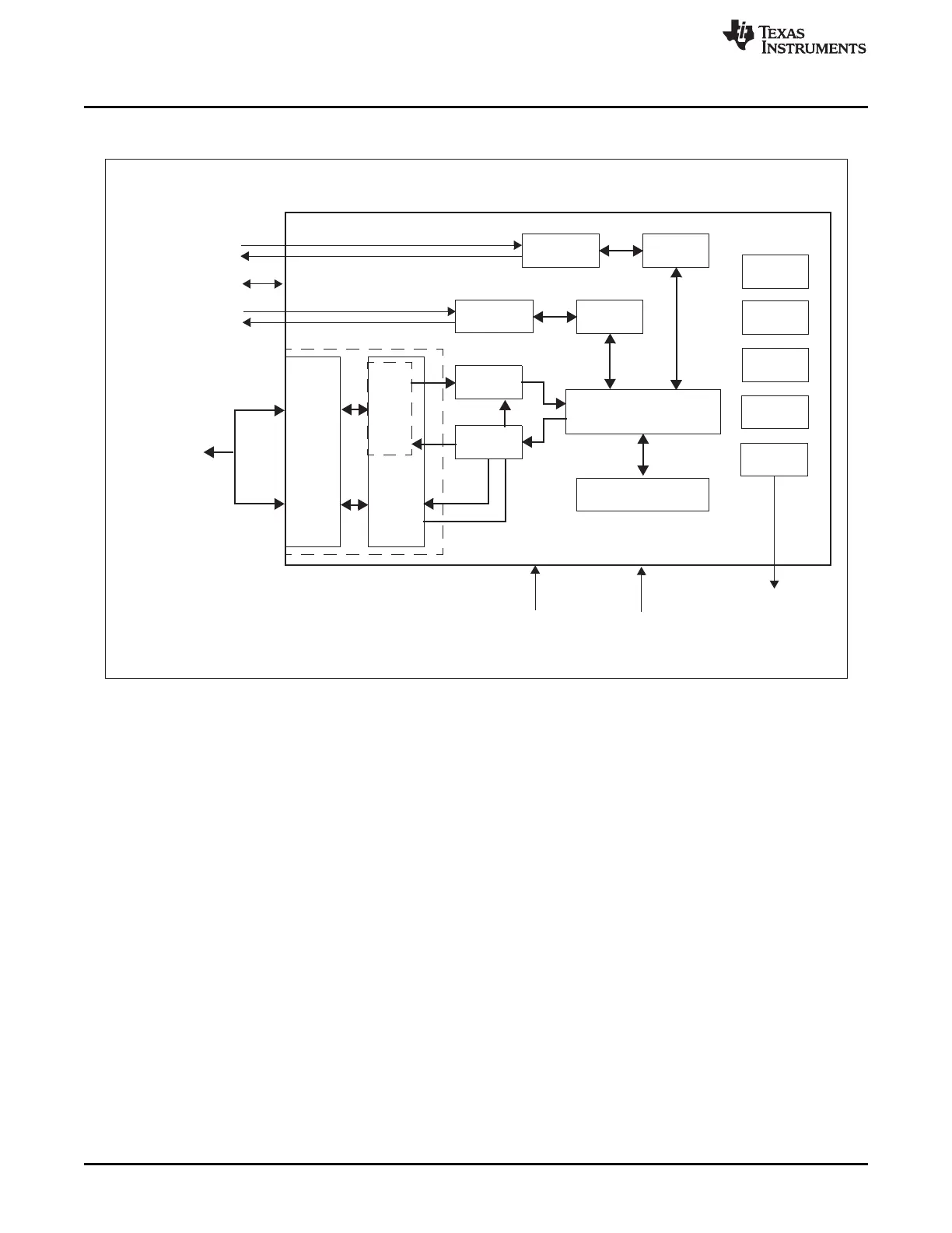
Figure 26-1. FlexRay Module Block Diagram
• Input Buffer (IBF)
For write access to the message buffers configured in the message RAM, the CPU or the FTU can
write the header and data section for a specific message buffer to the input buffer. The message
handler then transfers the data from the input buffer to the selected message buffer in the message
RAM.
• Output Buffer (OBF)
For read access to a message buffer configured in the message RAM the message handler transfers
the selected message buffer to the output buffer. After the transfer has completed, the CPU or the FTU
can read the header and data section of the transferred message buffer from the output buffer.
• Message Handler (MHD)
The message handler controls data transfers between the following components:
– Input / output buffer and message RAM
– Transient buffer RAMs of the two FlexRay protocol controllers and message RAM
• Message RAM
The message RAM stores up to 128 FlexRay message buffers together with the related configuration
data (header and data partition).
• The Transient Buffer RAM (TBF A/B):
Stores the data section of two complete messages.

 Loading...


