T
enter
T2
T6
T3 T5
WAKEUP
WAKEUP
SEND
WAKEUP
LISTEN
WAKEUP
DETECT
T4
T
exit
READY
WAKEUP
STANDBY
T1
www.ti.com
Module Operation
1235
SPNU563A–March 2018
Submit Documentation Feedback
Copyright © 2018, Texas Instruments Incorporated
FlexRay Module
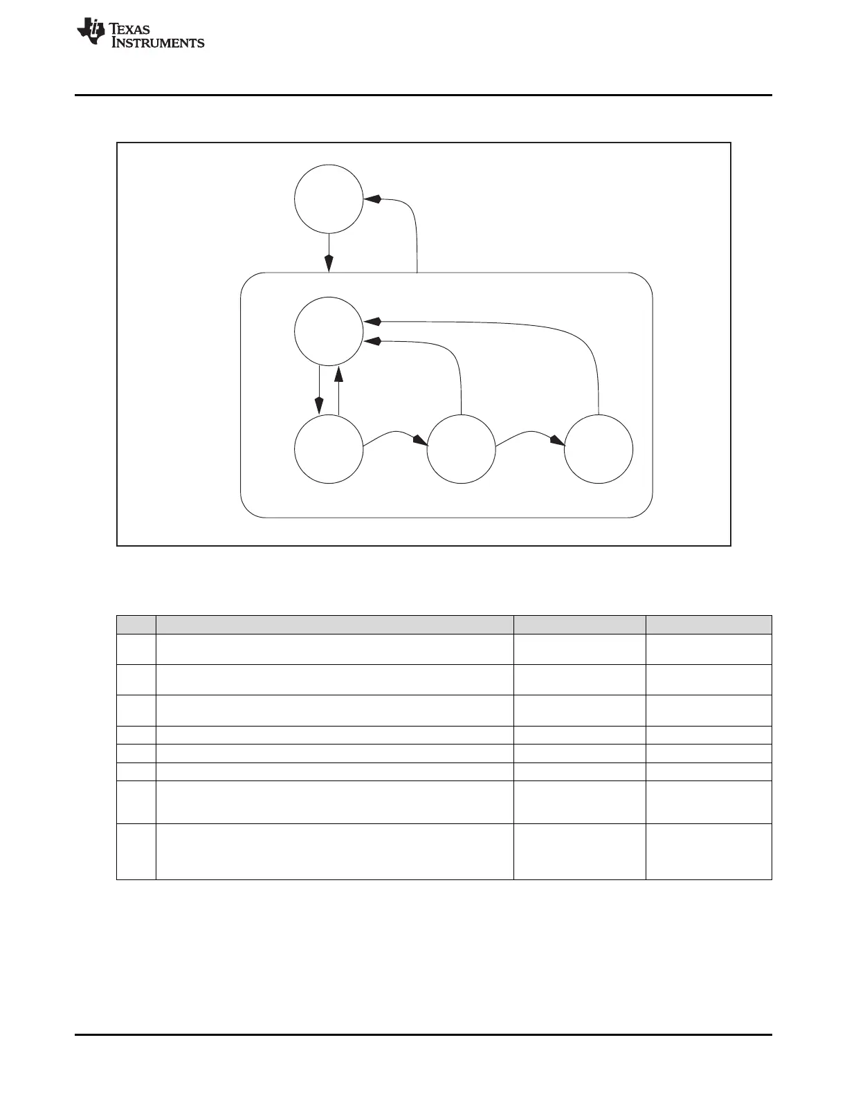
Figure 26-13. Structure of POC State WAKEUP
Table 26-7. State Transitions WAKEUP
T# Condition From To
enter Host commands change to WAKEUP state by writing SUCC1.CMD(3-
0) = 0011 (WAKEUP command)
READY WAKEUP
1 CHI command WAKEUP triggers wakeup FSM to transit to
WAKEUP_LISTEN state
WAKEUP_STANDBY WAKEUP_LISTEN
2 Received WUP on wakeup channel selected by bit SUCC1.WUCS OR
frame header on either available channel
WAKEUP_LISTEN WAKEUP_STANDBY
3 Timer event WAKEUP_LISTEN WAKEUP_SEND
4 Complete, non-aborted transmission of wakeup pattern WAKEUP_SEND WAKEUP_STANDBY
5 Collision detected WAKEUP_SEND WAKEUP_DETECT
6 Wakeup timer expired OR WUP detected on wakeup channel selected
by bit SUCC1.WUCS OR frame header received on either available
channel
WAKEUP_DETECT WAKEUP_STANDBY
exit Wakeup completed (after T2 or T4 or T6) OR host commands change
to READY state by writing SUCC1.CMD(3-0) = 0010 (READY
command). This command also resets the wakeup FSM to
WAKEUP_STANDBY state.
WAKEUP READY
The WAKEUP_LISTEN state is controlled by the wakeup timer and the wakeup noise timer. The two
timers are controlled by the parameters Listen Timeout SUCC2.LT(20-0) and Listen Timeout Noise
SUCC2.LTN(3-0). Listen timeout enables a fast cluster wakeup in case of a noise free environment, while
listen timeout noise enables wakeup under more difficult conditions regarding noise interference.

 Loading...


